Daktronics AB-1600-1.5,2.5 User Manual
Page 54
4-12
Maintenance & Troubleshooting
4. Pull the lampbank from the lens/reflector assembly.
Complete the following steps to replace a lampbank.
1. Place the lampbank on the lens/reflector assembly. The white power connector (J1) should be
to the right side (rear view).
2. Press down upon each latch bracket until both the latch arms on each latch snap into position.
3. Reconnect the two lampbanks on the lens/reflector assembly with the ribbon cable.
4. Put the lens/reflector back into the display cabinet as explained in Lens/Reflector Assemblies
in Section 4.3.
In the event a lamp socket needs to be replaced on a lampbank, complete the following steps in a
static-free environment.
1. Unsolder the two contacts of the socket.
2. Carefully pull the socket from the lampbank. Take care not to damage the pad or lift the trace.
3. Insert the new socket and solder in place.
4. Clean the area of solder residue and apply conformal coating to the circuit board to protect
against moisture damage. Use PC-101 protective coating for circuit boards (or equivalent).
SE-1003 is the Daktronics part number for such coating.
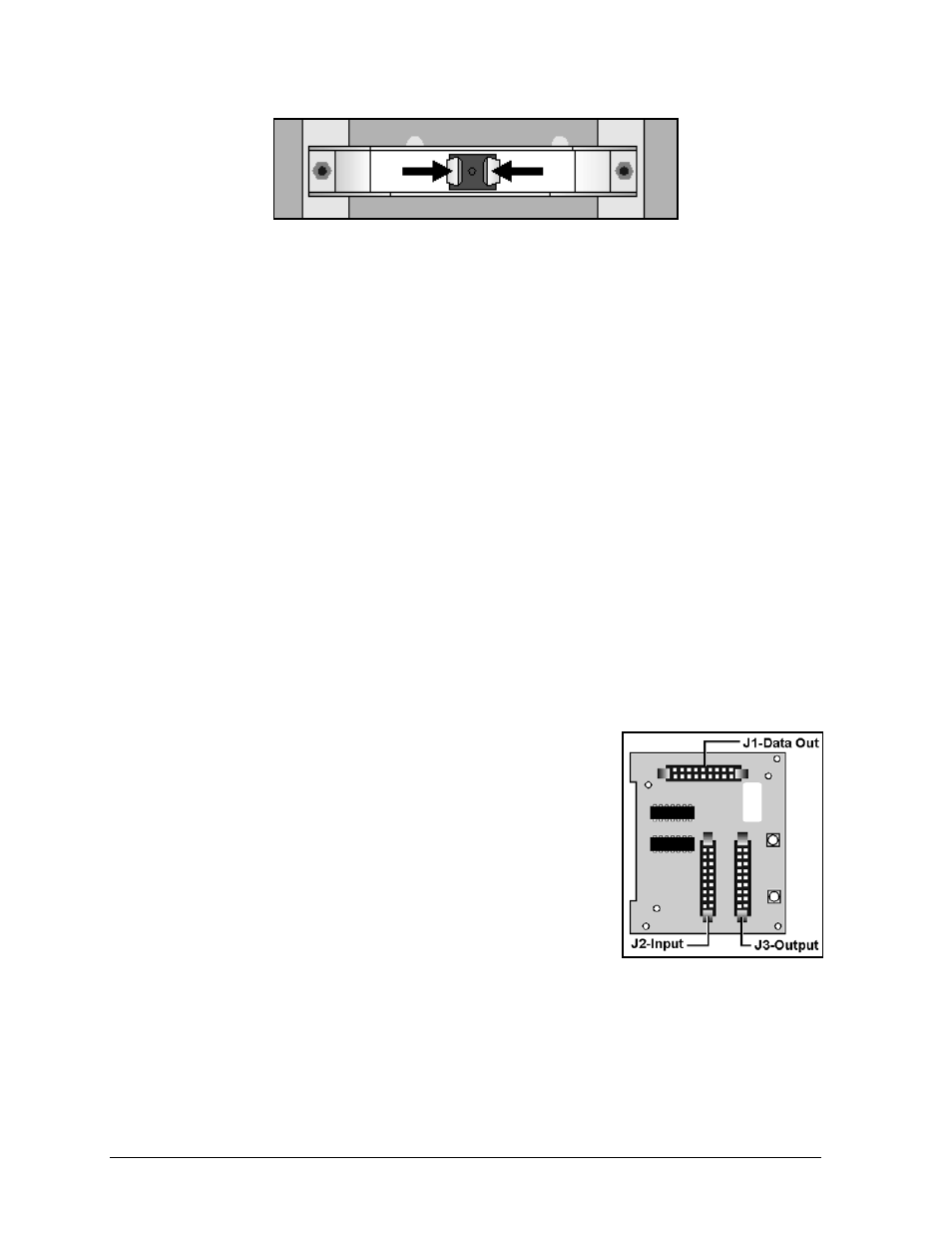
Vertical Shift Boards
A vertical shift board (VSB) is found on the back on the left-most lampbank in each row. It routes
incoming data down each row of lampbanks. The top VSB within a display receives data from one
of two locations.
•
If Venus 1500 controlled, data comes from the master/echo
board in the fan control enclosure of the master display.
•
If Venus 4600 controlled, data comes from the serial line
interface board in that display.
All other VSBs receive data from the VSB above it.
Figure 54 illustrates a vertical shift board. The table lists the
function of each of the labeled components.
Figure 53: Lampbank Latch
Figure 54: VSB
Components