Section 3: electrical installation – Daktronics AB-1600-1.5,2.5 User Manual
Page 23
Electrical Installation
3-1
Section 3: Electrical Installation
Appendix B contains two copies of the Installation Quality Checklist. It covers both mechanical and
electrical installation. This form assists in display installation and assures its dependable operation.
Address each item on the checklist. Following installation, return one copy to Daktronics Customer
Service to receive a free set of replacement air filters. Contact Daktronics Customer Service if any
product quality questions or concerns should arise.
3.1 Common
Connectors
This display uses many different types of connectors for power and signal termination. Take special
care when disengaging any connector so as not to damage the connector, the cable or the circuit board.
When pulling a connector plug from a jack, do not pull on the wire or cable; pull on the jack
itself. Pulling on the wires may damage the connector.
The following information presents some common connectors encountered during display
maintenance. These include ribbon cable connectors, Mate-n-Lok connectors, Phoenix-style
connectors, fiber optic connectors, termination panels and termination blocks, and tab connectors.
Some displays do not use all of these connectors.
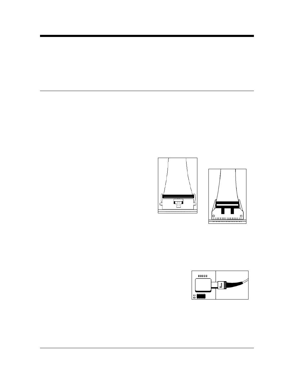
1. Ribbon Cable Connectors:
Daktronics uses a variety of ribbon cables and
ribbon cable connectors. Figure 29 and Figure 30
show two of the most common ribbon cable
connectors. To disconnect ribbon cable connector
#1, squeeze the metal locking clips inward and
pull the plug out of the jack. To disconnect ribbon
cable connector #2, pull each of the plastic
locking arms outward and remove the plug.
Before replacing a ribbon cable connector, spray
it with DeoxIT
™
contact cleaner to remove any foreign matter that may
cause signal problems. In addition, apply a generous amount of CaiLube
™
protector paste to the plug before inserting it into the jack. This paste will protect both the plug
and the jack from corrosion. Both the DeoxIT and the CaiLube are in the tool kit accessories
package included with this display. Refer to the replacement parts list in Section 4.15 if additional
supplies of either are needed.
2.
Fiber Optic Connectors:
At each end of a fiber optic cable is a “twist-on” connector. To
remove the fiber plug from its jack, push it toward the jack and
twist it counter-clockwise until the plug can pull free. Figure 31
shows a common type of fiber optic connector.
Figure 29: Ribbon
Cable Connector 1
Figure 30: Ribbon
Cable Connector 2
Figure 31: Fiber Optic
Connector