Daktronics AB-1600-1.5,2.5 User Manual
Page 53
Maintenance & Troubleshooting
4-11
2. Slide the lens/reflector assembly back into position in the cabinet. A firm push should be all
that is needed to lock the assembly into position. Give a tug to the assembly to verify that it is
firmly locked in place.
3. If necessary, replace any lenses as explained in Lenses in Section 4.3.
If one or both sides of the lens/reflector assembly fail to lock into position after repeated attempts
take the following steps.
1. Hold a section of 2x4 board vertically against the louvers on the stubborn side of the
assembly.
2. With the heel of the other hand strike the board
3. Give a tug to the assembly to verify the assembly is locked in place.
Do not pound on the board with a hammer or similar device. This is likely to damage the
louvers.
Lampbanks
A lampbank is a circuit board consisting of an array
of lamps eight pixels high by four pixels wide.
There are two lampbanks mounted on the rear of
each lens assembly. When a lampbank is placed on
the back of the lens/reflector assembly, the lamps
extend into holes in the back of the reflector shells,
allowing the reflectors and louvers to direct the
light. Section 4.3, Figure 48 illustrates this.
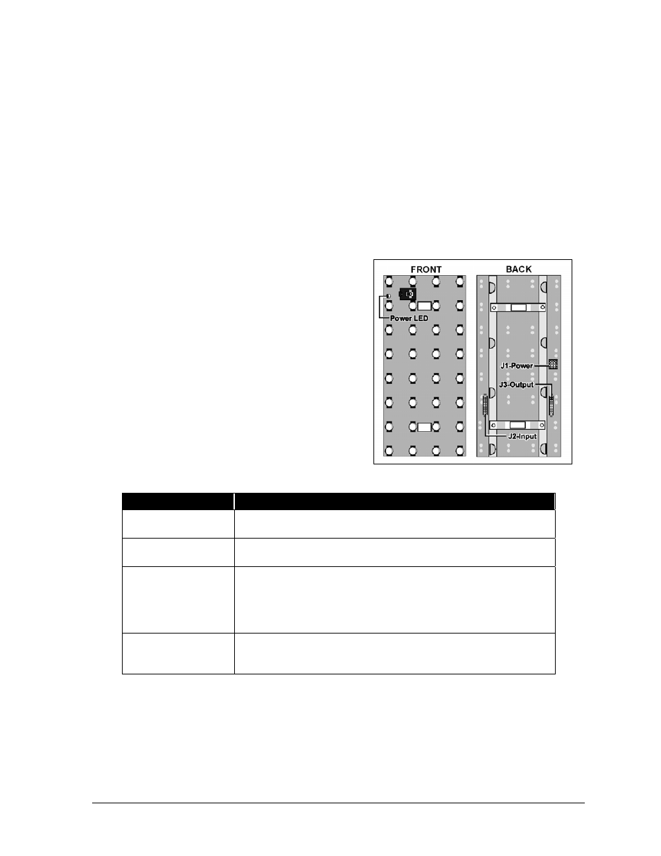
A single lampbank, front and back, is shown in
Figure 52. The functions of the labeled components
are explained in the following table.
Component
Function
Power LED
A lit LED indicates the lampbank is receiving its operational
voltage of 5 VDC.
J1-Power
Power from a transformer enters the lampbank at this
connector.
J2-Input
Signal enters the lampbank at this connector from any of the
following sources:
•
From a vertical shift board if it is the left-most lampbank in
any row (front view).
•
From the previous lampbank in that row.
J3-Output
Signal exits the lampbank at this connector and is passed to
the next lampbank in that row. This connector is not used on
the last lampbank in any row.
Complete the following steps to remove a lampbank from a lens/reflector assembly.
1. Remove the appropriate lens/reflector assembly as explained in Lens/Reflector Assemblies in
Section 4.3.
2. Disconnect the ribbon cable connecting the two lampbanks.
3. Each lampbank is held to the lens/reflector assembly by two plastic latches. One latch at a
time, squeeze the latch arms together and pull that end of the lampbank up past the latch.
Refer to Figure 53.
Figure 52: Lampbank Components