Daktronics AB-1600-1.5,2.5 User Manual
Page 65
Maintenance & Troubleshooting
4-23
sharply with the brightly lit pixels. The louvers also help direct light from the pixels.
The louvers require no maintenance. However, replace severely bent or damaged louvers to
maximize display effectiveness.
Note: As noted on the replacement parts list in Section 4.15, the top louver of a lens/reflector
assembly has a different part number than the other 6 or 7 (depending on display model) louvers
below it. Take care to order the correct louver.
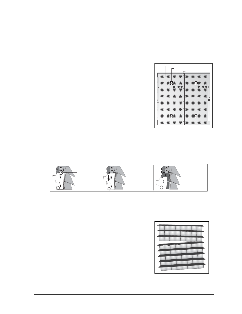
Refer to Figure 65 and complete the following steps to
replace a louver.
1. Remove the lens/reflector assembly from the cabinet as
explained in Lens/Reflector Assemblies in Section 4.3.
2. Remove both the lampbanks from the back of the
lens/reflector assembly as explained in Lampbanks in
Section 4.3.
3. Remove the lampbank latches by removing the single
screw that holds each one in place.
4. Remove the vertical bracket by removing the 7 or 8
screws (depending on display model) that hold it in place.
5. The metal rain shield is now free to be slid upward and off
from the lens/reflector assembly.
6. On both top corners of the assembly is a retaining tab bent
over the top louver. With pliers, bend each of these tabs back in alignment with the metal side
plates. Figure 66 shows the method used to position the side plates for louver replacement.
7. Push each metal side plate downward until it is free to pull away from the assembly.
Replacing only the top louver does not require the removal of the side metal plates.
8. Having removed the side plates, the only thing holding the rows of louvers/reflector together
is the tape weather stripping between them. Access the damaged louver by pulling the rows
above this louver off in an intact group, as Figure 67
illustrates. There are now two groups of row/reflector
assemblies.
9. In the same manner as done with the metal side brackets,
slide the damaged louver to the side and remove it from
the row of reflectors beneath it. Discard it returning it to
Daktronics.
10. Place the new louver onto the reflector row and slide it to
the side until it secures in place beneath the top reflector
tabs.
11. Remove the protective tape from the tape weather
stripping to expose the adhesive surface. Nothing,
especially hands, should touch the exposed adhesive
surface of the weather stripping. The top louver of an assembly does not have tape weather
stripping.
Vertical Bracket
Lampbank Latch
Metal Rain Shield
Figure 65: Lens Assembly
Components
Bend back
retaining tabs on
upper corners
Push each metal
side plate
downward
Pull each metal
side plate off
the assembly
Figure 66: Removing a Metal Side Plate
Figure 67: Separating Rows
above Damaged Louver