Daktronics AB-1600-1.5,2.5 User Manual
Page 35
Electrical Installation
3-13
3.7
Interconnect of 2V Displays
Reference Drawing:
Interconnect, 2V
Drawing A-104023
Shop Drawing, 7 or 8 High, 2 ½
˝
..........................................................Drawing A-114666
Shop Drawing, 16 High, 2 ½
˝
................................................................Drawing A-114667
Shop Drawing, 24 High, 2 ½
˝
................................................................Drawing A-114668
The procedure for interconnecting 2V displays differs for Venus 1500 and Venus 4600 systems.
Drawing A-104023 provides a general idea how signal cable routes between display faces in both
Venus 1500 and Venus 4600 systems.
In order to provide a signal interconnect between two (or more) Venus 1500 system displays the
lens/reflector assemblies must be removed from in front of both the Venus 1500 display controller and
the fan control enclosure. Venus 4600 systems do not have a fan control enclosure. Therefore, remove
only the lens/reflector assemblies in front of the serial line interface.
The shop drawing for this display shows the locations of the display controller (Venus 1500 controller
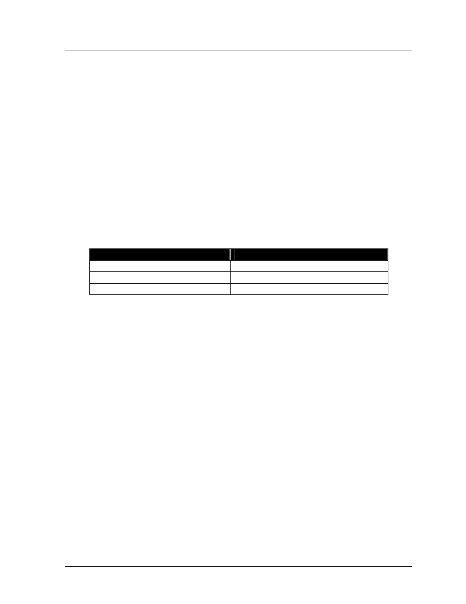
or serial line interface) and the fan control enclosure (Venus 1500 only). The following table explains
which shop drawing is used for which display.
If the display being installed is…
Consult shop drawing…
7 or 8 high display (all lengths)
Drawing A-114666
16 high display (all lengths)
Drawing A-114667
24 high display (all lengths)
Drawing A-114668
Refer to Lens/Reflector Assemblies in Section 4.3 for instructions on removing lens/reflector
assemblies.
Having removed the needed lens/reflector assemblies, proceed to the appropriate sub-section for this
display.
Venus 1500 Systems
On all Venus 1500 systems, signal comes from the controller computer to the Venus 1500
controller in the independent (master) display. That signal then relays to the echo display over two
25-foot-long cables: one being 12-pin and the other being 20-pin.
The two 25-foot cables ship in the echo display. The location of the cables within the display is
labeled on the back sheet.
When placed back-to-back, the displays can have a maximum separation of five feet if the display
is 144 pixels long. For every 16 pixels less in length, the displays can be two feet farther apart.
Complete the following steps to interconnect signal between the master and echo displays.
1. Route two-inch conduit and both the 12 and 20-pin cables between the displays. Daktronics
provides knockouts on the rear of the displays for attaching conduit.
2. Within the echo display, the 20-pin connector plugs into the “Input” jack of the vertical shift
board located at the upper-left end (front view) of the display. The vertical shift board attaches
to the back of the lampbank of the rear of the lens/reflector assembly. Eight-pixel-high
displays only have one lens/reflector assembly on the left end of the display.
3. Still within the echo display, the 12-wire cable routes from TB31 into the 12-position jack of