Daktronics AB-1600-1.5,2.5 User Manual
Page 60
4-18
Maintenance & Troubleshooting
Complete the following steps to replace a fiber optic board:
1. Turn off display power at the power disconnect.
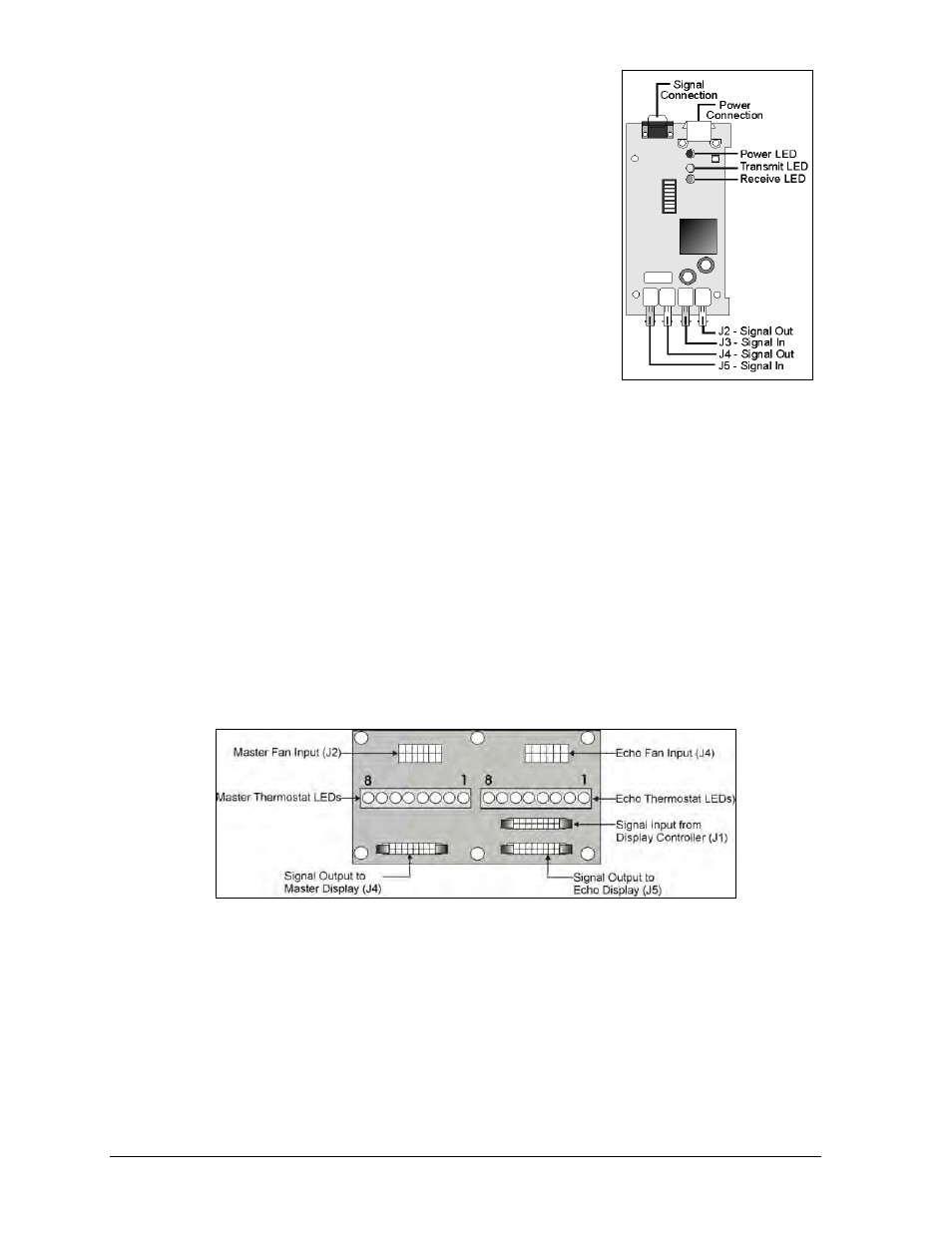
2. Disconnect the power and signal connections. Figure 60
illustrates the fiber optic board connectors.
3. Carefully remove the four nuts holding the fiber optic
board in place.
4. Install the new fiber optic board, replace the nuts and
reconnect power and signal cables.
Master-Echo Board
Inside the fan controller enclosure of the Venus 1500 display is
the master-echo board, illustrated in Figure 61. This circuit
board serves as a relay. It receives display data from the Venus
1500 controller and routes it to the vertical shift boards of both
the master and, if present, the echo display. The master-echo
board is only in the master display fan controller enclosure.
In addition to routing display signal, the master-echo board also monitors the button
thermostats of both the master and, if present, the echo display. If internal cabinet
temperatures climb too high, one or more thermostats will open. The master-echo board will
sense this and send an alert to the Venus 1500 controller, which will blank the display.
When the internal cabinet temperature drops to acceptable levels, the thermostats will close,
the master-echo board will alert the Venus 1500 controller of the change and will restore
normal display operation.
The master-echo board has 16 LEDs to indicate thermostat status – eight for the master face
and eight for the echo face. Each of these groups of LEDs are numbered 1 – 8, right to left.
These LEDs correspond to button thermostats with the display cabinet, which number 1 – 8,
left to right, when viewed from the front.
Complete the following steps to remove a master-echo board from its enclosure.
1. To access the fan control enclosure housing the master-echo board, remove the necessary
lens/reflector assemblies as explained in Lens/Reflector Assemblies in Section 4.3. Refer
to the shop drawing listed in Section 4.2 if unsure of the location of the controller on this
display.
2. Remove the cover from the enclosure.
3. Disconnect all signal cables from the circuit board. It may be helpful to label the
connectors to ensure correct placement when installing another master-echo board.
4. Remove the nuts holding the board in place and remove the board from the enclosure.
Figure 60: Optional Fiber
Optic Board
Figure 61: Master-Echo Board Components