Daktronics AB-1600-1.5,2.5 User Manual
Page 19
Mechanical Installation
2-3
When mounting the display take note of the following:
•
Keep ½-inch clearance below the drain holes in the bottom of the display.
•
Do not obstruct airflow to the display fans. Refer to Drawing A-114676.
•
Power and signal terminations require access to the inside of the display. Avoid mounting the
display in a manner that hinders access to the display face.
•
The Daktronics engineering staff must first approve any modifications to the display ventilation
system.
You must properly seal the eyebolt holes on top of the display cabinet to prevent water from
entering the unit and damaging the electrical components.
Complete the following steps if leaving the eyebolts in the display.
1. Verify the eyebolts are firmly in place. From time to time eyebolts will loosen slightly from
shipping vibration.
2. If the eye bolts need tightening, keep in mind they need only be snug. Over-tightening will crush
the rubber sealing washers, rendering then ineffective.
3. Apply silicone sealant around the base of the eyebolts on top of the cabinet.
Complete the following steps if removing the eyebolts from the display.
1. Remove and discard the eyebolts, but keep the rubber sealing washers.
2. To plug the eyebolt holes, insert half-inch bolts through the rubber sealing washers and into the
eyebolt holes from the top of the display cabinet.
3. Tighten the bolt only as much as is needed to hold the bolt snugly in place. Over-tightening will
crush the rubber sealing washers, rendering then ineffective.
4. On the top of the cabinet, apply silicone sealant around the head of each bolt.
Inspect the entire display for any holes or gaps that may allow
water to enter the display. Use silicone sealant to close any such
openings.
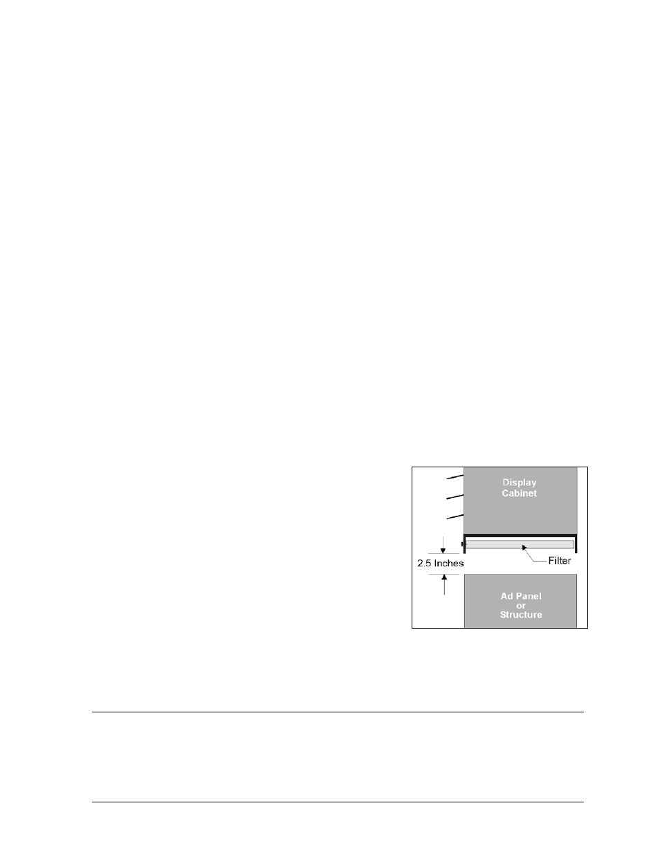
The filters of 1600 series small matrix display are located on the
bottom exterior of the display cabinet. If mounting an
advertising panel or other structure beneath this display, 2.5
inches of clearance must be present in order to remove the
filters. Refer to Figure 26.
The amount of clearance between the display and the ad panel
or structure can also affect display ventilation. Refer to Section
2.5 to calculate the amount of clearance required for adequate
display cooling.
Filter removal is addressed in Section 4.3, Filters.
2.4
Light Detector and Temperature Sensor Installation
Refer to ED9490 in Appendix C for light detector installation and ED9489 in Appendix C for
temperature sensor installation information.
Figure 26: Bottom Clearance