Daktronics AB-1600-1.5,2.5 User Manual
Page 38
3-16
Electrical Installation
difference between the two options is the number of wires running from the sensor to the Venus
A/B transmitter interface, where the sensor connects.
Complete the following steps to connect the photo/temp sensor to the Venus A/B transmitter
interface.
1. Remove the cover from the Venus A/B transmitter interface. Removing
each of the two screws on the face of the enclosure and lifting the cover
away accomplishes this.
2. Route cable and conduit from the sensor to the A/B interface.
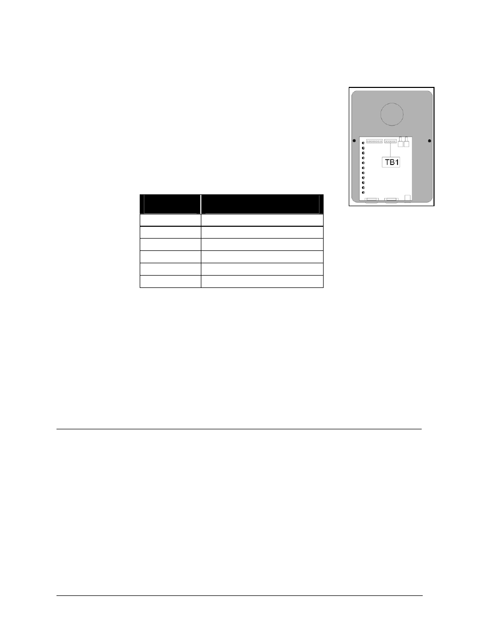
3. Strip the wire insulation and terminate to TB1 in the A/B interface as shown
in the table below. Figure 39 illustrates the location of TB1 on the A/B
interface circuit.
The wire colors correspond to the wire colors leaving the sensor.
Wire
Color
TB1 On A/B Interface
Circuit Board
White
Pin 1 (Photo-P)
Black
Pin 2 (GND-N)
Red
Pin 3 (TMPV-P)
Brown
Pin 4 (GND-N)
Green
Pin 5 (TMPIN-P)
Shield
Pin 6 (GND-N)
Not all wires above will be present if the temperature sensor is not included. If this is the case,
simply connect the wires that are present according to the above table.
Proceed to Section 3.10 if all the following statements are true.
• Signal from the controller computer routes and connects to the serial line interface within the
display.
• The photo/temp sensor ordered with the display has connected to the A/B transmitter
interface.
• If this is a 2V, multi-face display, signal has interconnected between the displays.
3.9
Optional External Temperature Sensor
Both Venus 1500 and Venus 4600 systems offer an optional external temperature sensor. This sensor
relays temperature information to the Venus software, which can then display the temperature data on
the display. This can be combined with the time to create a “time and temp” service.
Operation instructions for the Venus 1500 and Venus 4600 software are in ED9067 and ED4602,
respectively. Use the appropriate software manual to configure the display if using a temperature
sensor.
Optional Temp Sensor Installation - Venus 1500 Systems
Instructions for mounting and connecting signal wire to the temperature sensor are located with
the temp sensor in its box.
Connect the temp sensor to the Venus 1500 display controller as follows.
Figure 39: TB1 on A/B
Interface