Daktronics AB-1600-1.5,2.5 User Manual
Page 39
Electrical Installation
3-17
1. Route the temp sensor cable (Daktronics part number W-1234) through conduit and into the
display.
2. Continue the cable into the controller box fitting labeled “TEMP.”
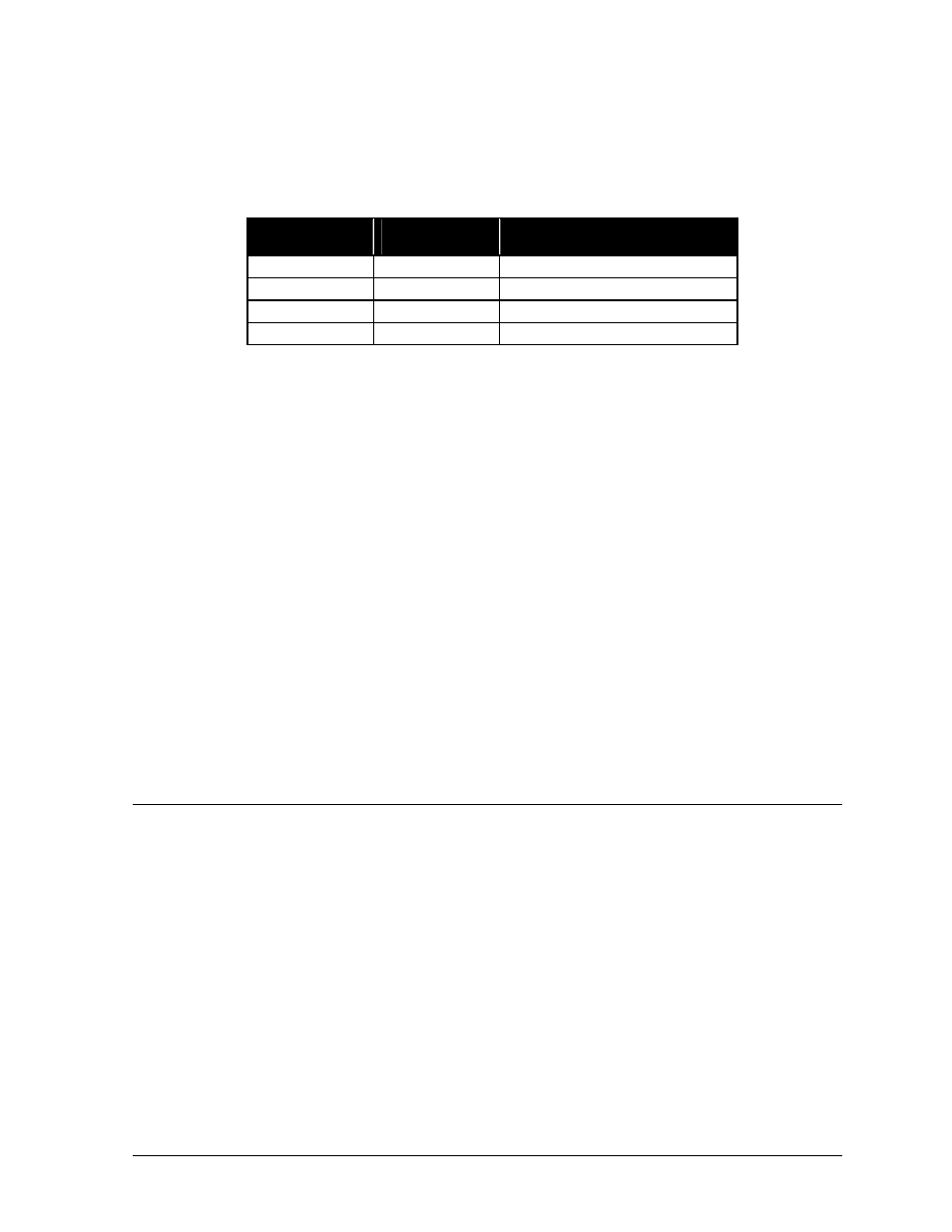
3. Strip the insulation and terminate wires to TB7 as shown below. TB7 is found near the lower-
right corner of the Venus 1500 controller product board, as seen in Figure 35 in Light
Detector Installation - Venus 1500 Systems in Section 3.8.
Temp
Detector
Field
Cabling
Venus 1500 Controller Term
Block (TB7)
P
Green
Pin 5 (Temp - P)
N White
Pin
6
(Temp - N)
+V Red
Pin
7
(+5V)
GND Black
Pin
8
(GND)
Proceed to Section 3.10 if all the following statements are true.
•
Signal from the controller computer has routed and connected to the Venus 1500 controller
within the display.
•
The light detector and/or temp sensor ordered with the display have connected to the Venus
1500 controller.
•
If this is a 2V, multi-face display, signal has interconnected between the displays.
Optional Photo/Temp Sensor Installation - Venus 4600 Systems
Instructions for mounting and connecting signal wire to the light detector are located with the light
detector in its box.
Venus 4600 systems usually have a combination light and temperature sensor. The two devices
integrate into a common circuit board. There is also a photocell-only option available. The only
difference between the two options is the number of wires running from the sensor to the Venus
A/B transmitter interface, where the sensor connects.
Refer to Optional Temp Sensor Installation - Venus 1500 Systems in Section 3.9 for photo/temp
sensor installation instructions.
3.10 First Time Power-Up
Having completed all power and signal connections, the display is now ready to power up for the first
time.
Before powering-up the display replace all enclosure covers within the display and put the
lens/reflector assemblies back into the cabinet. If additional instructions are needed refer to Signal
Summary in Section 4.2 for a general overview of signal connection within the display and
Lens/Reflector Assemblies in Section 4.3 for instructions on removing and replacing a lens/reflector
assembly.
Having re-assembled the display, turn the display ON at the main disconnect and verify the following
occurs on the display.