Daktronics AB-1600-1.5,2.5 User Manual
Page 46
4-4
Maintenance & Troubleshooting
From the master-echo board, display information goes to the vertical shift board located
behind the upper-left-most lampbank (front view). A 20-pin ribbon cable connects J4 (Master
Output) on the master-echo board to J2 (Input) on the vertical shift board. If an echo display is
present, data is sent to the same vertical shift board on that display via J5 (Echo Output) on
the master-echo board.
The vertical shift board then sends the display information to the lampbank on which it is
mounted. A 20-pin ribbon cable connects J1 (Data Out) on the vertical shift board to J2
(Input) on the lampbank. On 16 and 24-high displays, J3 (Output) on each vertical shift board
connects to J2 (Input) on the vertical shift board below it. Each display row has one vertical
shift board behind the left-most lampbank (front view).
The display data then cascades down the row as it is passed from J3 (Output) on each
lampbank to J2 (Input) on the next lampbank over 20-pin ribbon cable.
The button thermostats in this display connect to a junction panel within the fan controller
enclosure before routing to J2 (Master Fans) on the master-echo board. If an echo display is
present, the button thermostats in that display connect to a junction panel in that display’s fan
control enclosure. However, only the master display has a master-echo board, so the
thermostat harness from the echo display routes to J3 (Echo Fans) on the master display’s
master-echo board.
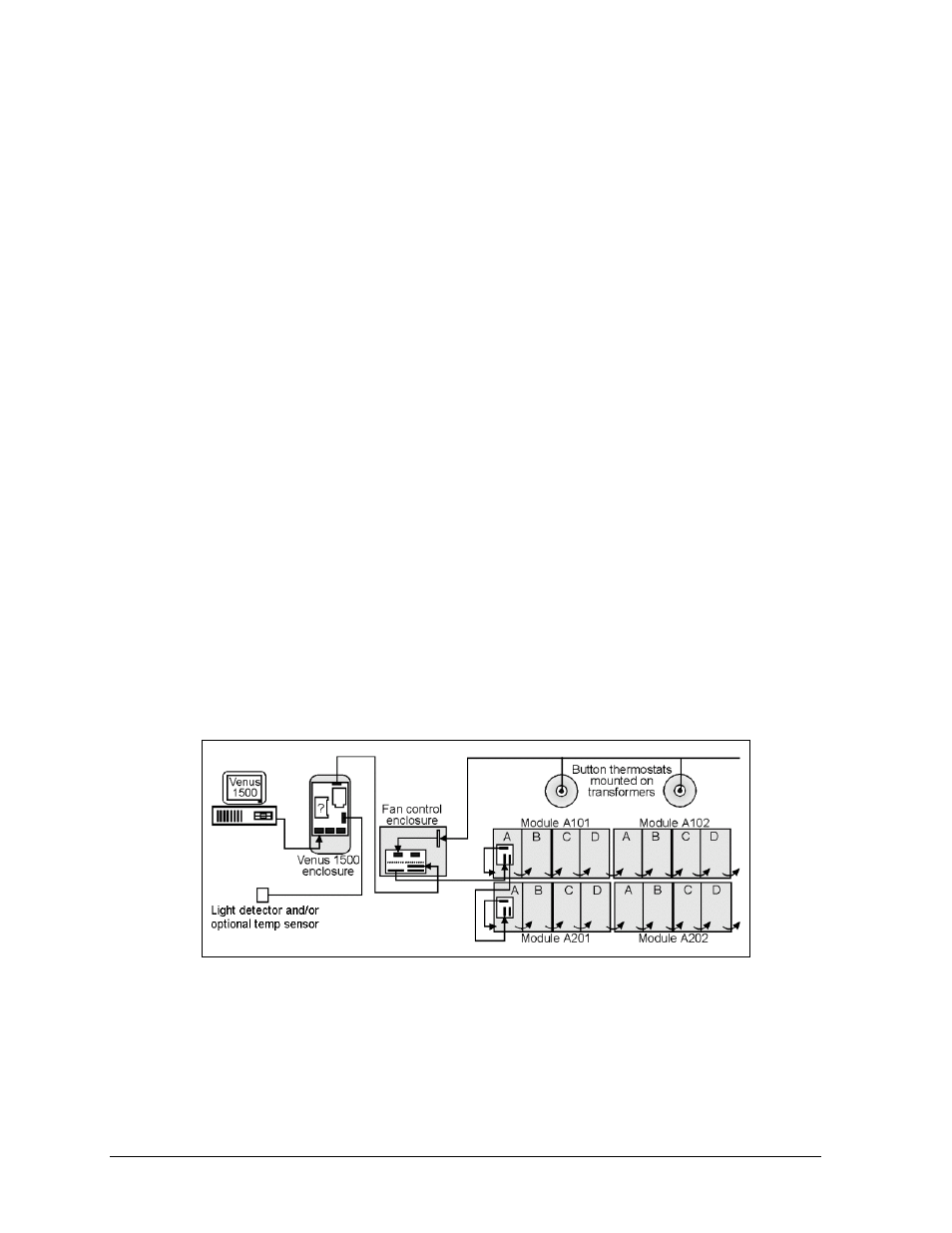
The light detector and the optional temp sensor connect to the Venus 1500 controller board at
TB7.
Figure 43 illustrates the signal routing for a Venus 1500, 16-high display. The illustration is
for conceptual purposes only. The display cabinet houses all components except the controller
computer and the light detector.
For detailed power and signal information, refer to the appropriate general schematic at the
end of this section, or the project specific schematic in Appendix A, if one was included.
Refer to Section 4.2 if unsure which schematic to use.
Venus 4600 Signal Summary
Signal routing for Venus 4600 systems starts at the controller computer. This computer,
running Venus 4600 software, sends data to the Venus A/B transmitter interface over serial
cable. The DB15 male-to-male cable connects to the A/B transmitter at J1.
The data then goes to the serial line interface board within the display over fiber optic cable.
The cable runs from the J5 fiber transmit jack within the A/B interface to the J6 fiber input
Figure 43: Signal Routing for Venus 1500, 16-High Display