Ltc connectors pinouts – Grass Valley K2 System Guide v.9.0 User Manual
Page 264
Advertising
Description
Signal
Pin #
Frame Ground
GND
1
Differential Transmit Data (low)
-TXD
2
Differential Receive Data (high)
+RXD
3
Transmit Signal Common
GND
4
Spare
NC
5
Receive Signal Common
GND
6
Differential Transmit Data (high)
+TXD
7
Differential Receive Data (low)
-RXD
8
Signal Ground
GND
9
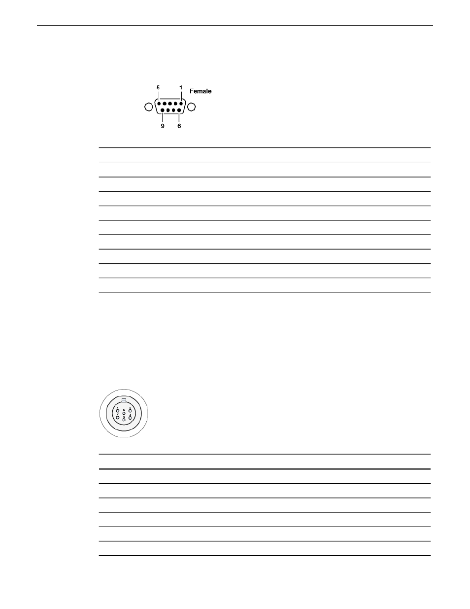
LTC connectors pinouts
The K2 Summit/Solo system LTC panel connector provides balanced linear timecode input and
output connections. The interface conforms to SMTPE 12M Linear Timecode.
On the K2 Summit/Solo system there is one 6 pin Switchcraft TRA6M Mini-XLR male connector
for each channel. Pinouts are as follows:
Description
Signal
Pin #
IN_P<0>
1
IN_N<0>
2
Frame Ground
GND
3
OUT_P<0>
4
OUT_N<0>
5
Frame Ground
GND
6
264
K2 System Guide
06 November 2012
Connector pinouts
Advertising
This manual is related to the following products: