5 auto-tuning, Types of auto-tuning, Auto-tuning for induction motors – Yaskawa L1000E AC Drive Technical Manual for CIMR-LE Models for Elevator Applications User Manual
Page 109
4.5 Auto-Tuning
YASKAWA ELECTRIC SIEP YAIL1E 01A YASKAWA AC Drive L1000E Technical Manual
109
St
ar
t-
U
p
Pr
og
ra
m
m
in
g
&
Op
er
at
io
n
4
4.5 Auto-Tuning
WARNING! Sudden Movement Hazard. The drive and motor may start unexpectedly during Auto-Tuning, which could result in death or
serious injury. Ensure the area surrounding the drive motor and load are clear before proceeding with Auto-Tuning. Remove main
power from the drive before servicing the drive or motor. Do not touch the motor during Auto-Tuning.
Note: When using a PM motor for the first time, or when replacing the drive or PM motor, always make sure that motor parameters are
set properly and the speed detection functions accurately prior to operation. Using a PM motor requires that the encoder offset be
set correctly in addition to entering motor data to corresponding parameters. If the motor, encoder, or drive are ever replaced, be
sure to perform Encoder Offset Auto-Tuning.
Insufficient torque can cause the elevator car to move in the direction of the load, or cause the motor to behave erratically
(reverse operation, stand still, sudden accelerations, etc.).
For more information, refer to the instruction manual included with the motor.
◆ Types of Auto-Tuning
The drive offers different types of Auto-Tuning for induction motors and permanent magnet motors. The type of Auto-
Tuning used differs further based on the control mode and other operating conditions. Refer to the tables below to select
the type of Auto-Tuning that bests suits the application. Directions for performing Auto-Tuning are listed in
Note: The drive will only show Auto-Tuning parameters that are valid for the control mode that has been set in A1-02. If the control
mode is for an induction motor, the Auto-Tuning parameters for PM motors will not be available. If the control mode is for a PM
motor, the Auto-Tuning parameters for induction motors will not be available. Inertia Tuning and ASR Gain Tuning parameters
and setting options will be visible only when the drive is set for operation with CLV or CLV/PM.
■
Auto-Tuning for Induction Motors
This feature automatically sets the V/f pattern and motor parameters E1- and E2- for an induction motor.
Additionally, the feature also sets some F1- parameters for speed feedback detection in Closed Loop Vector.
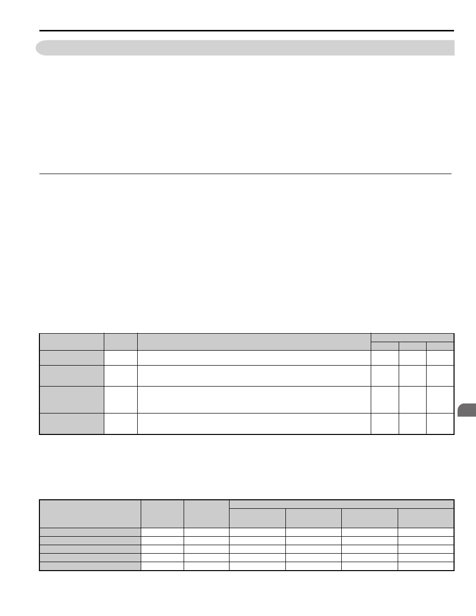
Table 4.5 Types of Auto-Tuning for Induction Motors
lists the data that must be entered for Auto-Tuning. Make sure this data is available before starting Auto-
Tuning. The necessary information is usually listed on the motor nameplate or in the motor test report provided by the
motor manufacturer. Also refer to
Flowchart B: Auto-Tuning for Induction Motors on page 106
for details on Auto-
Tuning process and selections.
Table 4.6 Auto-Tuning Input Data
Type
Setting
Requirements and Benefits
Control Mode (A1-02)
V/f (0)
OLV (2)
CLV (3)
Rotational Auto-Tuning
T1-01 = 0
• Rotational Auto-Tuning gives the most accurate results, and is recommended if possible.
• Motor must run freely or with light load (<30%), i.e. ropes have to be removed.
No
Yes
Yes
Stationary Auto-Tuning 1
T1-01 = 1
• A motor test report listing motor data is not available.
• Automatically calculates motor parameters needed for vector control.
• Use if ropes can not be removed. Note that the accuracy is less then with Rotational Auto-Tuning.
No
Yes
Yes
Stationary Auto-Tuning
for Line-to-Line Resis-
tance
T1-01 = 2
• Used for V/f Control or in vector control modes when the drive was previously set up properly and now
the motor cable has changed.
• Used in V/f control if drive and motor capacities differ.
• Should not be used for any vector control modes unless the motor cable has changed.
Yes
Yes
Yes
Stationary Auto-Tuning 2
T1-01 = 4
• A motor test report is available. Once the no-load current and the rated slip have been entered, the drive
calculates and sets all other motor-related parameters.
• Use if ropes can not be removed and if slip and no-load current data are available.
No
Yes
Yes
Input Value
Input Parameter
Unit
Tuning Type (T1-01)
0
Standard
1
Stationary 1
2
Line-to-Line
Resistance
4
Stationary 2
Control Mode
A1-02
–
2, 3
2, 3
0, 1, 2, 3
2, 3
Motor Rated Power
T1-02
kW
YES
YES
YES
YES
Motor Rated Voltage
T1-03
Vac
YES
YES
N/A
YES
Motor Rated Current
T1-04
A
YES
YES
YES
YES
Motor Rated Frequency
T1-05
Hz
YES
YES
N/A
YES