Replacing the drive – Yaskawa L1000E AC Drive Technical Manual for CIMR-LE Models for Elevator Applications User Manual
Page 329
7.5 Drive Replacement
YASKAWA ELECTRIC SIEP YAIL1E 01A YASKAWA AC Drive L1000E Technical Manual
329
Pe
ri
od
ic
In
spe
ct
io
n
&
Main
tenan
ce
7
◆ Replacing the Drive
WARNING! Electrical Shock Hazard. Do not connect or disconnect wiring while the power is on. Failure to comply can result in serious
personal injury. Before servicing the drive, disconnect all power to the equipment. The internal capacitor remains charged even after
the power supply is turned off. After shutting off the power, wait for at least the amount of time specified on the drive before touching
any components.
WARNING! Electrical Shock Hazard. Do not allow unqualified personnel to perform work on the drive. Failure to comply could result in
serious injury. Installation, maintenance, inspection and servicing must be performed only by authorized personnel familiar with
installation, adjustment and maintenance of AC drives.
NOTICE: Damage to Equipment. Observe proper electrostatic discharge procedures (ESD) when handling the drive and circuit boards.
Failure to comply may result in ESD damage to the drive circuitry.
The following procedure explains how to replace a drive. This section provides instructions for drive replacement only.
To install option cards or other types of options, refer to the specific manuals for those options.
NOTICE: When transferring a braking transistor, braking resistor, or other type of option from a damaged drive to a new replacement
drive, make sure they are working properly before reconnecting them to the new drive. Replace broken options to prevent immediate
break down of the replacement drive.
1.
Refer to Terminal Cover on page 59
for details.
Note: The shape of the terminal covers and the numbers of the screws differ depending on the drive models.
for details.
Figure 7.27
Figure 7.27 Drive Replacement: Removing the Terminal Cover
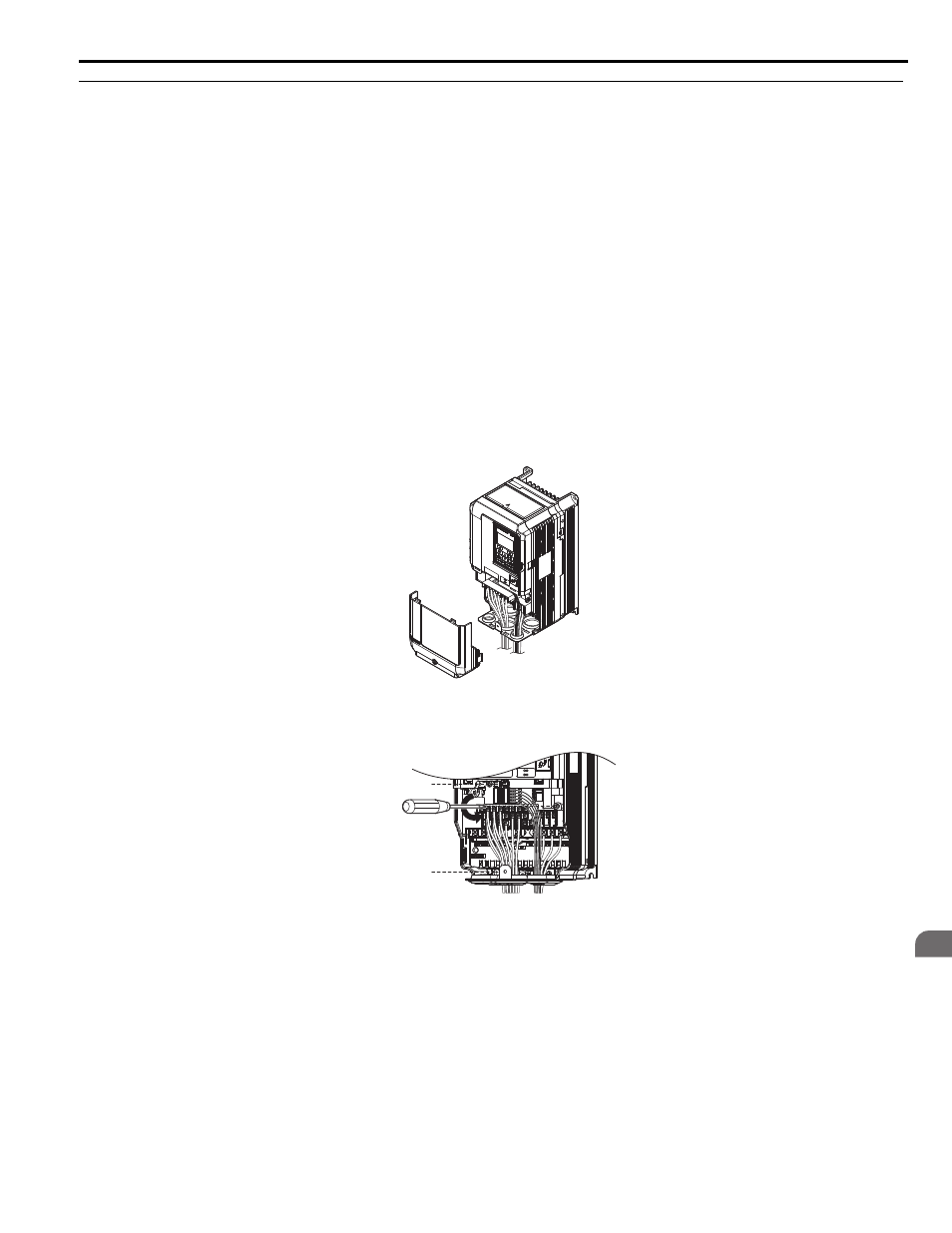
2.
Loosen the screws holding the terminal board in place. Remove the screw securing the bottom cover and remove
the bottom cover from the drive.
Figure 7.28
Figure 7.28 Drive Replacement: Removing the Control Terminal Board
YEA
_ c o
m m
YEA_c
ommo