L8-77: oscillation suppression, L8-88: safe disable operation mode, Common_ tmonly – Yaskawa L1000E AC Drive Technical Manual for CIMR-LE Models for Elevator Applications User Manual
Page 230: 8 l: protection functions, Overload tolerance for internal braking transistor, Setting 0: mode 0 setting 1: mode 1
5.8 L: Protection Functions
230
YASKAWA ELECTRIC SIEP YAIL1E 01A YASKAWA AC Drive L1000E Technical Manual
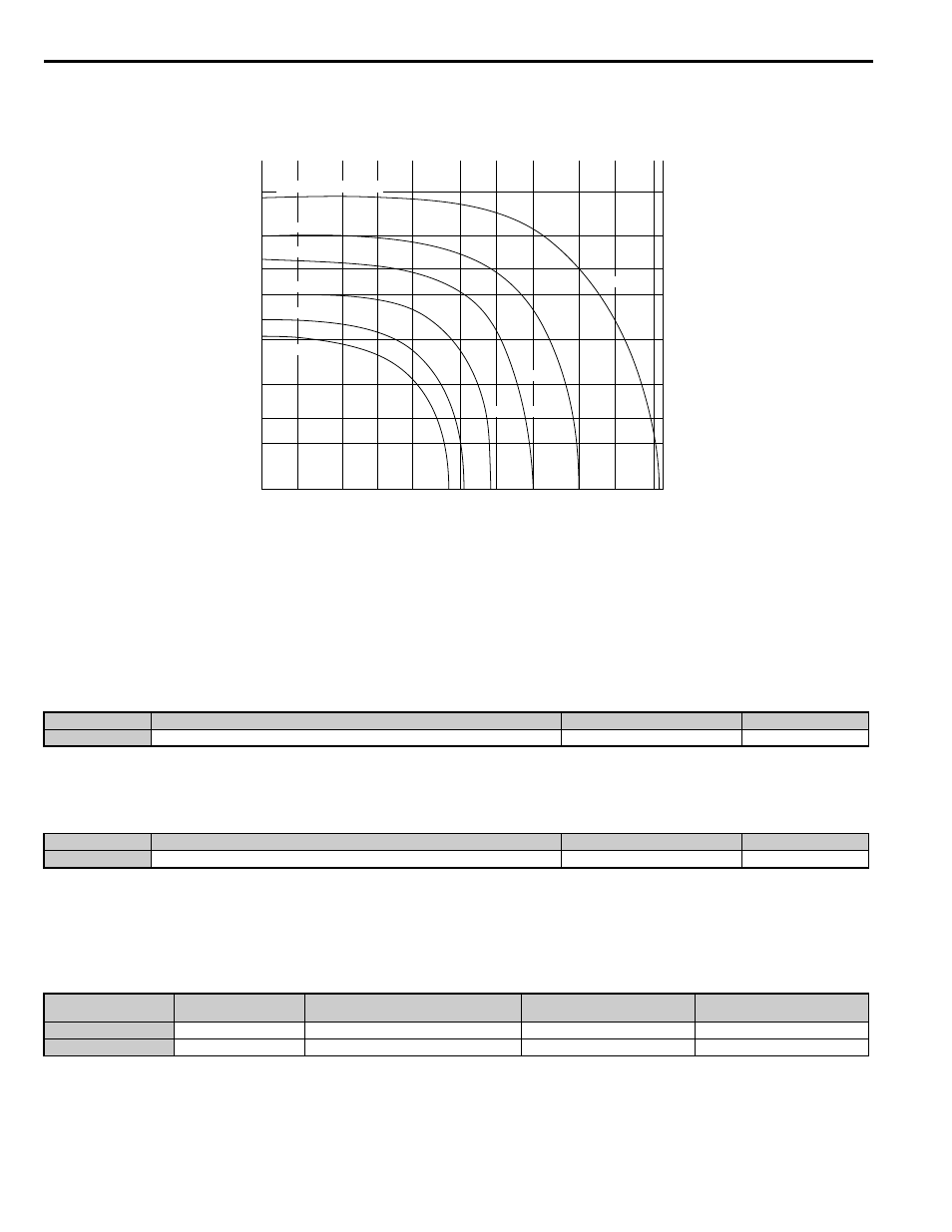
Overload Tolerance for Internal Braking Transistor
show the overload tolerance level for the drive’s built-in braking transistor.
Figure 5.42
Figure 5.42 Overload Tolerance for Braking Transistor (2A0018 to 2A0144 and 4A0009 to 4A0075)
■
L8-77: Oscillation Suppression
If speed oscillations with the same frequency as the output frequency occur with an unloaded motor, parameter L8-77 can
be adjusted to suppress these oscillations. While watching the motor speed, increase or decrease L8-77 until the
oscillation disappears.
This parameter rarely requires adjustment.
■
L8-88: Safe Disable Operation Mode
Determines the operation performed by the drive when the Safe Disable input is activated.
Setting 0: Mode 0
Setting 1: Mode 1
When the Safe Disabled Input is triggered, the operator displays and alarm, and the corresponding output terminal will
react as follows:
No.
Parameter Name
Setting Range
Default
L8-77
Oscillation Suppression
–100 to 100
0
No.
Parameter Name
Setting Range
Default
L8-88
Safe Disable Operation Mode
0 or 1
1
L8-88
Safe Disable Operation
Selection
Alarm Display during Safety Disable
Alarm Output (H2- = 10)
Drive Ready
(H2- = 6)
0 (mode 0)
Hbb
ALM flashes
ON
OFF
1 (mode1)
Hbb
ALM flashes
OFF
ON
100
%
50
30
20
10
5
3
2
Braking Torque = 30%
50%
70%
100%
130%
150%
1
10
2
5
200
500
1000
2000
100
50
20
Operation Time (s)
(%)
(%ED)
8
16
5
43
21
29
67
80
170
150
106
58
90
160
270
380
420
1200
600
1800
230
500
760
Usage
common_
TMonly