T the v/f pattern used for motor 2, For details on, Figure 5.16 – Yaskawa L1000E AC Drive Technical Manual for CIMR-LE Models for Elevator Applications User Manual
Page 195: Show, Yea_tmon, Common_ tmonly, 7 h: terminal functions
5.7 H: Terminal Functions
YASKAWA ELECTRIC SIEP YAIL1E 01A YASKAWA AC Drive L1000E Technical Manual
195
P
a
ra
me
te
r De
ta
ils
5
Figure 5.16
Figure 5.16 Fast Stop Sequence
NOTICE: Rapid deceleration can trigger an overvoltage fault. When faulted, the drive output shuts off, and the motor coasts. To avoid
this uncontrolled motor state and to ensure that the motor stops quickly and safely, set an appropriate Fast Stop time to C1-09.
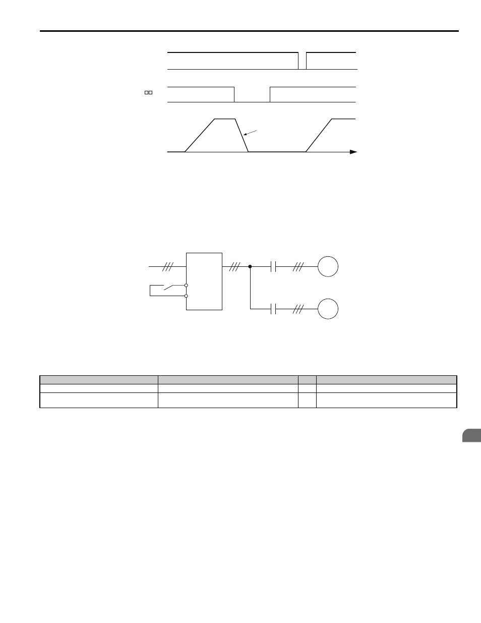
Setting 16: Motor 2 selection
The drive has the capability to control two induction motors independently. A second motor may be selected using a
multi-function digital input as shown in
Note: The motor 2 selection function cannot be used when PM motor is used.
Figure 5.17
Figure 5.17 Motor Selection
When switching between motor 1 and motor 2, the parameters used to control those motors also change. Below,
lists the parameters that correspond to each motor.
Table 5.11 Parameters for Switching Between Two Motors
Note: 1. The drive can switch from motor 2 to operate motor 1 in V/f Control based on the speed reference set for motor 2.
for details.
2. It is not possible to switch between motor 1 and motor 2 during run. Doing so will trigger the “rUn” alarm.
3. It is not possible to switch between motors when CLV/PM control mode is selected.
4. The motor 2 selection function is available only with OLV control mode (A1-02 = 0).
5. When switching from motor 1 to motor 2, check to make sure that motor 2 is operating.
If a digital output is programmed for “Motor 2 selection” (H1-01, H1-02, or H1-03 = 1C), motor will be selected when the
output is closed.
Setting 18: Timer function input
This setting configures a digital input terminal as the input for the timer function. Use this setting combination with the
timer function output (H2- = 12).
Refer to b4: Delay Timers on page 159
for details.
Setting 1A: Accel/decel ramp selection 2
Used to select accel/decel ramps 1 to 4 in combination with the Accel/decel ramp selection 1 command.
C1-08: Accel, Decel Ramps 1 to 4 on page 162
for details.
No.
Setting 16 Open (Motor 1)
⇒
Setting 16 Closed (Motor 2)
C1-: Acceleration/Deceleration Time
C1-01 to C1-04
⇒
C1-12 to C1-13
E1-, E3-: V/f Pattern
E2-, E4-: Motor Parameters
E1-, E3-
⇒
E3-, E4-
Up/Down/Stop
TIME
Fast Stop
Decelerates at C1-09
ON
ON
ON
ON
Output Speed
H1- = 17
YEA_TMon
M
M
Drive
Motor 1
Motor 2
Motor switch input
common_
TMonly