O: operator related parameters, Current detection adjustments, O1: digital operator display selection – Yaskawa L1000E AC Drive Technical Manual for CIMR-LE Models for Elevator Applications User Manual
Page 395: B.3 parameter table
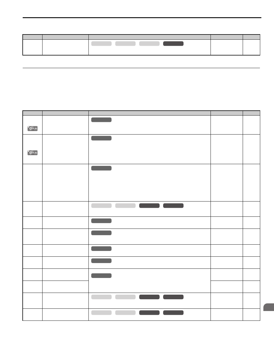
B.3 Parameter Table
YASKAWA ELECTRIC SIEP YAIL1E 01A YASKAWA AC Drive L1000E Technical Manual
395
Pa
ra
met
er
L
is
t
B
■
n9
:
Current Detection Adjustments
◆ o: Operator Related Parameters
The o parameters set up the digital operator displays.
■
o1: Digital Operator Display Selection
Refer to Digital Operator Display Unit Selection on page 105
for details on digital operator displays.
No. (Addr.)
Name
Description
Setting
Page
n9-60
(64DH)
<4> Default setting is determined by the drive model (o2-04).
A/D Conversion Start Delay
Sets a delay time for starting the current signal A/D conversion. This value seldom needs to be
changed.
Default:
Min: 0.0
μs
Max: 40.0
μs
No. (Addr.)
Name
Description
Setting
Page
o1-01
(500H)
Drive Mode Unit Monitor
Selection
Switches the display after the power has been turned on. When using an LED operator, pressing
the up arrow key will display the following data: frequency reference
→ rotational direction →
output frequency
→ output current → output voltage → U1-.
Default: 106 (Monitor
U1-06)
Min: 105
Max: 699
o1-02
(501H)
User Monitor Selection after
Power Up
o1-02 selects the information that is displayed when the power is turned on.
1: Speed reference (U1-01)
2: Direction
3: Output speed (U1-02)
4: Output current (U1-03)
5: User-selected monitor (set by o1-01)
Default: 1
Min: 1
Max: 5
o1-03
(502H)
Digital Operator Display Unit
Selection
Sets the units the drive should use to display the frequency reference and motor speed monitors.
0: 0.01 Hz
1: 0.01% (100% = E1-04)
2: r/min (calculated using the number of motor poles setting in E2-04, E4-04, or E5-04)
3: User-selected units (set by o1-10 and o1-11)
4: Elevator units 1 (speed in m/s, accel/decel rate and jerk in s)
5: Elevator units 2 (speed in m/s, accel/decel rate in m/s
2
, jerk in m/s
3
)
6: Elevator units 3 (speed in ft/min, accel/decel rate in ft/s
2
, jerk in ft/s
3
)
Default: 1
Min: 0
Max: 6
o1-04
(503H)
V/f Pattern Setting Units
0: Hz
1: r/min
Default:
Min: 0
Max: 1
o1-05
(504H)
LCD Contrast Control
Adjusts the brightness and contrast of the LCD screen on the digital operator.
Default: 3
Min: 0
Max: 5
o1-06
(517H)
User Monitor Selection Mode
0: 3 Monitor Sequential (Displays the next 2 sequential monitors)
1: 3 Monitor Selectable (o1-07 and o1-08 selected monitor is displayed)
Default: 0
Min: 0
Max: 1
o1-07
(517H)
Second Line Monitor Selection
Selects the monitor displayed on the second line.
Default: 102
Min: 101
Max: 699
o1-08
(517H)
Third Line Monitor Selection
Selects the monitor displayed on the third line.
Default: 103
Min: 101
Max: 699
o1-10
(520H)
User-Set Display Units Maximum
Value
These settings define the display values when o1-03 is set to 3.
o1-10 sets the display value that is equal to the maximum output frequency.
o1-11 sets the position of the decimal position.
Default:
Min: 1
Max: 60000
o1-11
(521H)
User-Set Display Units Decimal
Display
Default:
Min: 0
Max: 3
o1-12
(739H)
Length Units
0: Millimeter unit
1: Inch unit
Default: 0
Min: 0
Max: 1
o1-20
(575H)
Traction Sheave Diameter
Sets the traction sheave diameter for display unit calculations.
Default: 400 mm
Min: 100 mm
Max: 2000 mm
common
_
CLV
CLV/PM
V/f
OLV
All Modes
common
_
All Modes
common
_
All Modes
common
_
common
_
CLV
CLV/PM
V/f
OLV
All Modes
common
_
All Modes
common
_
All Modes
common
_
All Modes
common
_
All Modes
common
_
common
_
CLV
CLV/PM
V/f
OLV
common
_
CLV
CLV/PM
V/f
OLV