8 control circuit wiring, Control circuit connection diagram, Control circuit terminal block functions – Yaskawa L1000E AC Drive Technical Manual for CIMR-LE Models for Elevator Applications User Manual
Page 73: Input terminals
3.8 Control Circuit Wiring
YASKAWA ELECTRIC SIEP YAIL1E 01A YASKAWA AC Drive L1000E Technical Manual
73
El
ec
tr
ic
al
In
st
al
la
ti
o
n
3
3.8 Control Circuit Wiring
◆ Control Circuit Connection Diagram
Refer to Standard Connection Diagram on page 54
when wiring the drive control circuit terminals.
◆ Control Circuit Terminal Block Functions
Drive parameters determine which functions apply to the multi-function digital inputs (S3 to S8), multi-function digital
outputs (M1 to M6), multi-function photocoupler outputs (P1-C1, P2-C2), multi-function analog inputs (A1, A2), and
multi-function analog monitor output (FM, AM). The default setting is listed next to each terminal in
on page
.
NOTICE: Equipment Hazard. Improper equipment sequencing could shorten useful life of the electrolytic capacitors and circuit relays
of the drive. Refrain from switching an input contactor more often than once every 30 minutes. Normally the drive I/O should be used to
stop and start the motor.
WARNING! Sudden Movement Hazard. Always check the operation and wiring of control circuits after being wired. Operating a drive
with untested control circuits could result in death or serious injury.
WARNING! Sudden Movement Hazard. Confirm the drive I/O signals and external sequence before starting test run. Failure to comply
may result in death or serious injury.
NOTICE: Frequently switching the drive power supply to stop and start the motor can damage the drive.
NOTICE: To get the full performance life out of the electrolytic capacitors and circuit relays, refrain from switching the drive power
supply off and on more than once every 30 minutes. Frequent use can damage the drive. Use the drive to stop and start the motor.
Note: Do not solder the ends of wire connections to the drive. Soldered wiring connections can loosen over time. Improper wiring
practices could result in drive malfunction due to loose terminal connections.
■
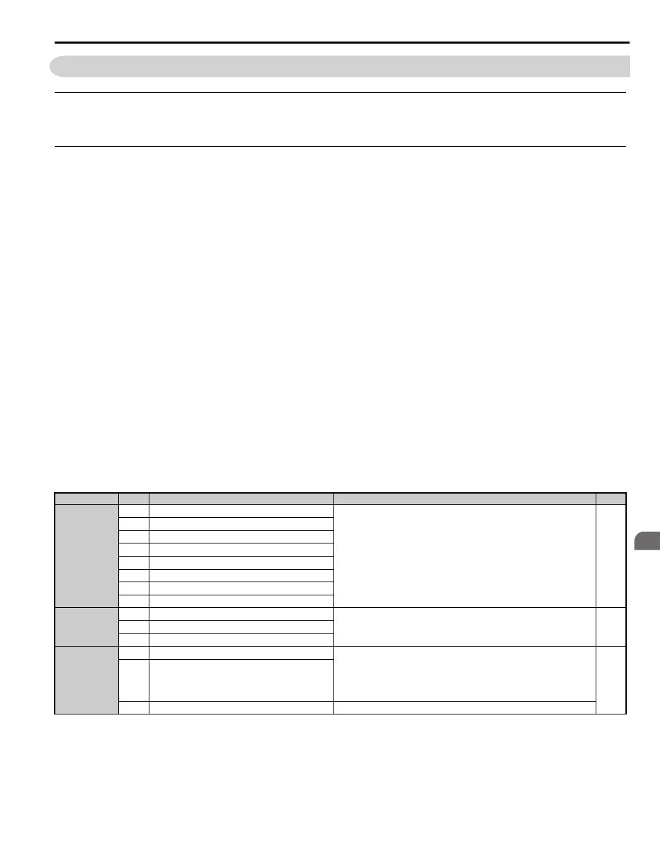
Input Terminals
lists the input terminals on the drive. Text in parenthesis indicates the default setting for each multi-function
input.
Table 3.5 Control Circuit Input Terminals
Type
No.
Terminal Name (Function)
Function (Signal Level) Default Setting
Page
Digital Inputs
S1
Up Command (Closed: Up, Open: Stop)
Photocoupler
24 Vdc, 8 mA
Use the wire link between terminals SC and SN or between SC and SP to select
sinking or sourcing, and to select the power supply.
S2
Down Command (Closed: Down, Open: Stop)
S3
Multi-function input 1 (External Fault)
S4
Multi-function input 2 (Fault Reset)
S5
Multi-function input 3 (Multi-Step Speed Reference 1)
S6
Multi-function input 4 (Multi-Step Speed Reference 2)
S7
Multi-function input 5 (Multi-Step Speed Reference 3)
S8
Multi-function input 6 (Not used)
Digital Input
Power Supply
SC
Multi-function input common
24 Vdc, 150 mA (only when DI-A3 is not used)
Use the wire jumper between terminals SC and SN or between SC and SP to select
sinking or sourcing, and to select the power supply.
SN
0 V
SP
+24 Vdc
Safe Disable
Inputs
H1
Safe Disable input 1
24 Vdc, 8 mA
One or both open: Drive output disabled
Both closed: Normal operation
Internal impedance: 3.3 k
Ω
Off time of at least 1 ms
Set the S3 jumper to select sinking or sourcing, and to select the power supply.
H2
Safe Disable input 2
HC
Safe Disable function common
Common for the Safe Disable function