5 operator programming errors – Yaskawa L1000E AC Drive Technical Manual for CIMR-LE Models for Elevator Applications User Manual
Page 296
6.5 Operator Programming Errors
296
YASKAWA ELECTRIC SIEP YAIL1E 01A YASKAWA AC Drive L1000E Technical Manual
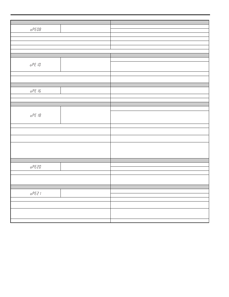
Digital Operator Display
Error Name
oPE08
Parameter Selection Error
A function has been set that cannot be used in the motor control method selected.
Cause
Possible Solutions
Attempted to use a function that is not valid for the selected control mode.
Check the motor control method and the functions available.
In Open Loop Vector Control, n2-02 is greater than n2-03
Correct parameter settings so that n2-02 is less than n2-03.
b1-14 (Phase Order Selection) is set to 1 (Switch phase order) when in using a PG option card. Correct the parameter settings.
Note: Use U1-18 to find parameters that are set outside the specified setting range. Other errors are given precedence over oPE08 when multiple errors occur simultaneously.
Digital Operator Display
Error Name
oPE10
V/f Pattern Setting Error
The following setting errors have occurred where:
E1-04 is greater than or equal to E1-06, E1-06 is greater than or equal to E1-07, E1-07 is
greater than or equal to E1-09, or E1-09 is greater than or equal to E1-11.
Cause
Possible Solutions
–
Correct the settings for E1-04, E1-06, E1-07, E1-09, and E1-11 (for motor 2, correct E3-04,
E3-06, E3-07, E3-09, and E3-11).
Digital Operator Display
Error Name
oPE16
Energy Savings Constants Error
Cause
Possible Solutions
Energy saving coefficients are out of the allowable range.
Check and correct the motor data in E5 parameters.
Digital Operator Display
Error Name
oPE18
Parameter Setting Error, Online Tuning Parameter Setting Error
• The input from load cell with load condition 1 (S3-29) is set to the same value as load
condition 2 (S3-30).
• DWELL 2 related parameters are not set correctly.
• Parameters that control Online Tuning are not set correctly.
Cause
Possible Solutions
S3-29 and S3-30 are set to the same value, meaning that the input from load cell with load
condition 1 (S3-29) is set to the same value as load condition 2 (S3-30).
Correct the values set to S3-29 and S3-30.
The Dwell 2 speed reference in S3-20 is greater than 0.00 but is still less than the Dwell 2 End
Speed in S3-21.
Correct the values set to S3-20 and S3-21.
Open Loop Vector Control is selected (A1-02 = 2), Online Tuning is enabled (n6-01 = 2), and
one of the following contradictory settings exists:
• E2-02 is set to 30% or less of its factory default.
• E2-06 is set to 50% or less of its factory default.
• E2-03 = 0
Correct the values set to E2-02, E2-03, or/and E2-06.
Digital Operator Display
Error Name
oPE20
PG-F3 Setting Error
The encoder signal frequency is too high.
Cause
Possible Solutions
With the entered encoder resolution (F1-01), maximum output frequency (E1-04), and motor
pole number (E5-04,) the calculation encoder signal frequency exceeds 50 kHz (with PG-F3
option) or 20 kHz (with PG-E3 option).
• Set F1-01 to the correct encoder resolution.
• Reduce the maximum output frequency of the drive in parameter E1-04 so the encoder
signal frequency at maximum speed is lower than 50 kHz.
Digital Operator Display
Error Name
oPE21
Elevator Parameter Setting Fault
Elevator parameters are not set correctly.
Cause
Possible Solutions
The DC Injection / Position Lock Time at Stop (S1-05) is set to a value lower than the Brake
Close Delay Time (S1-07).
Correct parameter settings so that S1-05 > S1-07.
• The deceleration distance (S5-11) is set to value lower than the minimum deceleration
distance (U4-43).
• The stop distance (S5-12) is set to a value lower than the minimum stop distance (U4-44).
• Correct parameter settings so that S5-11 > U4-43.
• Correct parameter settings so that S5-12 > U4-44.
Both S5-10 and S5-01 are enabled at the same time.
Correct the setting in parameters S5-01 and S5-10.