C6: carrier frequency, B.3 parameter table – Yaskawa L1000E AC Drive Technical Manual for CIMR-LE Models for Elevator Applications User Manual
Page 373
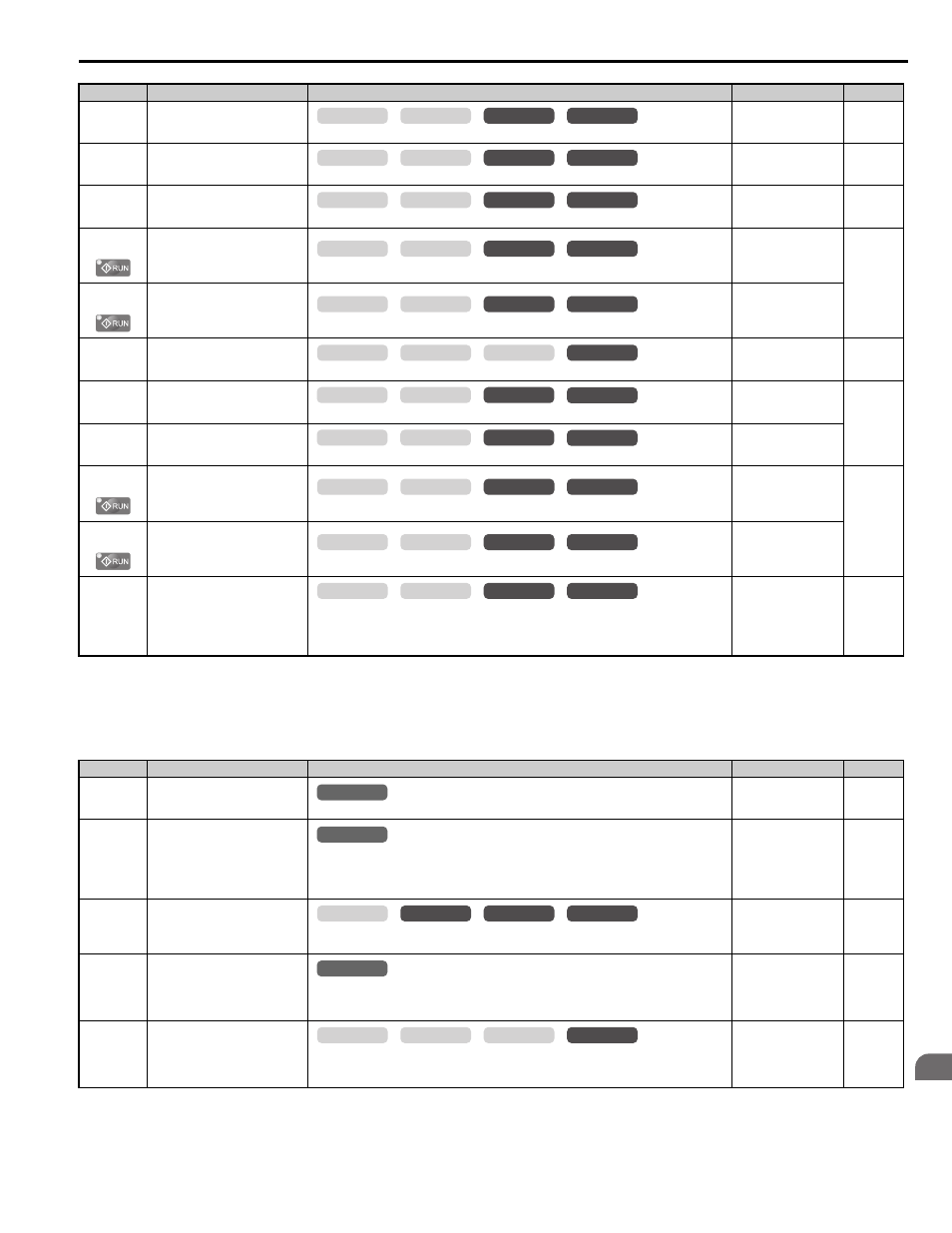
B.3 Parameter Table
YASKAWA ELECTRIC SIEP YAIL1E 01A YASKAWA AC Drive L1000E Technical Manual
373
Pa
ra
met
er
L
is
t
B
■
C6: Carrier Frequency
C5-06
(220H)
Speed Control Loop Primary
Delay Time Constant
Sets the filter time constant for the time from the speed loop to the torque command output.
Default: 0.004 s
Min: 0.000 s
Max: 0.500 s
C5-07
(221H)
Speed Control Settings Switching
Speed
Sets the speed for switching between proportional gain 1, 2, 3 and integral time 1, 2, 3.
Default:
Min: 0.0%
Max: 100.0%
C5-08
(222H)
Speed Control Loop Integral Limit
Sets the speed control loop integral upper limit as a percentage of rated torque.
Default: 400%
Min: 0%
Max: 400%
C5-13
(272H)
Speed Control Loop Proportional
Gain 3
Sets the proportional gain 3 of the speed control loop.
Default:
Min: 0.00
Max: 300.00
C5-14
(273H)
Speed Control Loop Integral Time
3
Sets the integral time 3 of the speed control loop.
Default:
Min: 0.000 s
Max: 10.000 s
C5-16
(271H)
Speed Control Loop Delay Time
during Position Lock
Sets a delay to the torque command output from speed control loop during Position Lock.
Default: 0.000 s
Min: 0.000 s
Max: 0.500 s
C5-17
(276H)
Motor Inertia
Sets the motor inertia.
Default:
Min: 0.0001 kgm
2
Max: 600.00 kgm
2
C5-18
(277H)
Load Inertia Ratio
Sets the ratio between the motor and load inertia.
Default: 1.0
Min: 0.0
Max: 6000.0
C5-19
(274H)
Speed Control Loop Proportional
Gain Time during Position Lock
Sets the Speed Control Loop Proportional gain used during Position Lock
Default:
Min: 0.00
Max: 300.00
C5-20
(275H)
Speed Control Loop Integral Time
during Position Lock
Sets the Speed Control Loop Integral time used during Position Lock.
Default: 0.100 s
Min: 0.000 s
Max: 10.000 s
C5-50
(B14H)
Set Vibrational Frequency
Sets the mechanical vibration filter frequency.
NOTICE: Test equipment may be required to determine the mechanical resonance frequency.
Setting C5-50 to an improper frequency will result in ineffective filtering of the effects of
mechanical resonance.
Default: 0 Hz
Min: 0 Hz
Max: 1000 Hz s
<1> Default setting is determined by the control mode (A1-02).
<2> Default setting value varies by the drive model (o2-04).
<3> Set this parameter to 0 to disable the notch filter. Frequencies from 1 to 19 Hz cannot be set.
No.(Addr.)
Name
Description
Setting
Page
C6-03
(225H)
Carrier Frequency
Sets the carrier frequency.
Default:
Min: 1.0 kHz
Max: 15.0 kHz
C6-06
(228H)
PWM Method
Selects PWM modulation method.
0: 2-phase/3-phase conversion
1: 2-phase modulation
2: 3-phase modulation
Default: 0
Min: 0
Max: 2
C6-09
(22BH)
Carrier Frequency during
Rotational Auto-Tuning
0: Carrier Frequency = 5 kHz
1: Setting value for C6-03
Default: 0
Min: 0
Max: 1
C6-21
(245H)
Inspection Operation Carrier
Frequency
Sets the carrier frequency during Inspection Run.
0: Setting value for C6-03
1: Carrier Frequency = 2 kHz
Default: 1
Min: 0
Max: 1
C6-23
(25EH)
Carrier Frequency during Initial
Motor Pole Search
Sets the carrier frequency when estimating the initial polarity.
0: Carrier Frequency = 2 kHz
1: Setting value for C6-03
Default: 0
Min: 0
Max: 1
No.(Addr.)
Name
Description
Setting
Page
common
_
CLV
CLV/PM
V/f
OLV
common
_
CLV
CLV/PM
V/f
OLV
common
_
CLV
CLV/PM
V/f
OLV
common
_
CLV
CLV/PM
V/f
OLV
common
_
CLV
CLV/PM
V/f
OLV
common
_
CLV
CLV/PM
V/f
OLV
CLV
CLV/PM
V/f
OLV
common
_
CLV
CLV/PM
V/f
OLV
common
_
common
_
CLV
CLV/PM
V/f
OLV
common
_
CLV
CLV/PM
V/f
OLV
common
_
CLV
CLV/PM
V/f
OLV
All Modes
common
_
All Modes
common
_
common
_
CLV
CLV/PM
V/f
OLV
All Modes
common
_
common
_
CLV
CLV/PM
V/f
OLV