S3: start/stop optimization, S3-03: position lock gain at stop, S3-04: position lock bandwidth – Yaskawa L1000E AC Drive Technical Manual for CIMR-LE Models for Elevator Applications User Manual
Page 251: S3-10: starting torque compensation increase time, 11 s: elevator parameters
5.11 S: Elevator Parameters
YASKAWA ELECTRIC SIEP YAIL1E 01A YASKAWA AC Drive L1000E Technical Manual
251
P
a
ra
me
te
r De
ta
ils
5
◆ S3: Start/Stop Optimization
■
S3-01 / S3-02: Position Lock Gain at Start 1 / 2
Sets gain levels 1 and 2 for the Position Lock at start function. Position Lock at start adjusts the internal torque reference
value depending on the position deviation to hold the car in place when the brake is released. S3-01 sets the gain used to
adjust the speed reference During Position Lock. S3-02 sets gain to adjust the internal torque reference directly (Anti-
Rollback function).
Increase S3-01 and S3-02 if there is a problem with rollback when the brake is released. Decrease S3-01 and S3-02 if
motor oscillation occurs during Position Lock.
Note: 1. Check the C5-
parameters to make sure the speed control loop settings are correct before making any adjustments to the Position
Lock gain.
2. Sometimes a fault may occur with detecting the direction of motor rotation (dv4) when using Closed Loop Vector for PM motors. To
correct this, either increase the settings of S3-01 and S3-02, or increase the number of pulses needed to trigger dv4 (F1-19).
■
S3-03: Position Lock Gain at Stop
Sets the gain used by the Position Lock control loop at stop to hold the car in place while the brake is applied.
Setting S3-03 to a high value will increase the ability of the drive to hold the car in place. Setting S3-03 too high can
cause motor oscillation and car vibration.
Note: 1. Check the C5-
parameters to make sure the speed control loop settings are correct before making any adjustments to the Position
Lock gain.
2. Faults may occur when detecting the direction of motor rotation (dv4) when using CLV/PM. To correct this, either increase the
settings of S3-01 and S3-02, or increase the number of pulses required to trigger dv4 (F1-19).
■
S3-04: Position Lock Bandwidth
Determines the bandwidth around the locked position to enable a digital output set for H2- = 33 (within position lock
bandwidth). The output will be triggered when the car moves from the Position Lock start point to plus or minus the
number of pulses set to S3-04.
■
S3-10: Starting Torque Compensation Increase Time
Sets a time constant for the torque reference to reach 300%. Enabled by setting an analog input terminal for torque
compensation (H3- = 14).
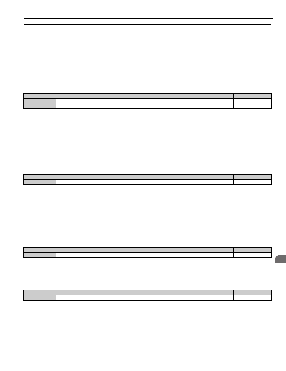
No.
Parameter Name
Setting Range
Default
S3-01
Position Lock Gain at Start 1
0 to 100
5
S3-02
Position Lock Gain at Start 2 (Anti-Rollback Gain)
0.00 to 100.00
0.00
No.
Parameter Name
Setting Range
Default
S3-03
Position Lock Gain at Stop
0 to 100
5
No.
Parameter Name
Setting Range
Default
S3-04
Position Lock Bandwidth
0 to 16383
10
No.
Parameter Name
Setting Range
Default
S3-10
Starting Torque Compensation Increase Time
0 to 5000 ms
500 ms