Riding comfort related problems, Riding, 7 setup troubleshooting and possible solutions – Yaskawa L1000E AC Drive Technical Manual for CIMR-LE Models for Elevator Applications User Manual
Page 145
4.7 Setup Troubleshooting and Possible Solutions
YASKAWA ELECTRIC SIEP YAIL1E 01A YASKAWA AC Drive L1000E Technical Manual
145
St
ar
t-
U
p
Pr
og
ra
m
m
in
g
&
Op
er
at
io
n
4
◆ Encoder Offset (E5-11) Set during Auto-Tuning (Rotational or Stationary)
Consistently Differs by 30 Degrees or More
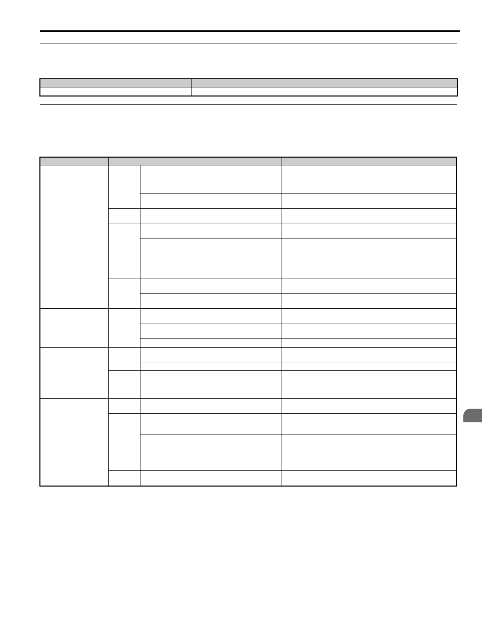
◆ Riding Comfort Related Problems
The following table describes the most common problems related to ride comfort and proposes countermeasures to those
problems. Before taking any action, make sure the startup procedures have been performed as previously described.
Cause
Possible Solutions
PG-E3 option position error with the ERN1387 encoder.
Perform Auto-Tuning of PG-E3 encoder characteristics (T2-01 = 12).
Problem
Control Mode and Possible Cause
Corrective Action
Rollback at start
V/f and OLV
Insufficient torque when the brake is released.
• Increase the DC Injection Braking Current at Start using parameter S1-02.
• Increase the Minimum Output Frequency Voltage (E1-10) and Medium
Output Frequency Voltage (E1-08) V/f pattern voltages. Make sure, that the
starting and leveling current does not rise too high.
DC Injection and brake timing is not optimized.
Set the time for DC Injection Braking at Start (S1-04) as short as possible, and
make sure that brake releases completely before the motor starts to turn.
OLV
The slip or torque compensation function acts too slowly.
• Decrease the Torque Compensation Time (C4-02).
• Decrease the Slip Compensation Time (C3-02).
CLV
CLV/PM
The speed control is not responding fast enough when the
brake is released.
Adjust the speed control loop parameters used During Position Lock. Increase
C5-19 and reduce C5-20.
The Position Lock control loop does not respond fast enough.
• Adjust the speed control loop parameters used During Position Lock.
Increase C5-19 and reduce C5-20.
• Increase the Position Lock Gain at Start 1 in S3-01 gradually. If vibration
occurs reduce it.
• Increase the Position Lock Gain at Start 2 in S3-02 gradually until rollback
disappears.
All
Motor torque is not fully established when the brake is
released.
Lengthen the Brake Release Delay Time (S1-06) and the time for DC
Injection Braking / Position Lock at Start (S1-04).
Motor contactor closes too late.
Make sure that the contactors are closed before the Up/Down command is
issued.
Shock at start
All
Motor starts turning when the brake is not completely released
or runs against the brake.
Increase the DC Injection Braking Time at Start using parameter S1-04.
Acceleration rate is changing too quickly.
Decrease the Jerk at Start. Decrease C2-01 if set in m/s
2
, increase C2-01 if set
in s.
Rollback occurs during brake release.
Refer to “Rollback at start”.
Shock at stop
All
Brake is applied too early, causing the motor to run against the
brake.
Increase the Delay Time to Close the Brake (S1-07). If necessary, also
increase the DC Injection Braking Time at Stop S1-05.
Motor contactor is released before the brake is fully applied.
Check the motor contactor sequence.
CLV
CLV/PM
Rollback occurs before the brake applies at stop.
• Make sure the speed control loop parameters for position lock are adjusted
properly (C5-13 and C5-14).
• Increase the Position Lock Gain at Stop S3-03 gradually until no rollback
occurs. If vibration occurs reduce the gain S3-03.
Jerk occurs due to overshoot
when the motor reaches top
speed.
OLV
Too fast torque or slip compensation.
• Increase the Torque Compensation Delay Time (C4-02).
• Increase the Slip Compensation Delay Time (C3-02).
CLV
CLV/PM
Speed control loop setting is too soft or too hard.
• Adjust the Speed Control Loop Gain C5-01 and Integral Time C5-02.
• Adjust Inertia Compensation parameters (n5-) if speed control loop
settings can not solve the problem
Incorrect motor data.
• For induction motors readjust the motor data (E2- ), especially the slip
(E2-02) and no-load current values (E2-03), or perform Auto-Tuning again.
• For PM motors readjust the motor data in E5- or perform Auto-Tuning.
Inertia compensation function is not set up correctly.
If the Inertia Compensation Function is used (n5-01=1) make sure the values
in n5-02 and n5-03 are correct.
All
The acceleration rate changes too quickly when reaching the
selected speed.
Decrease the Jerk at the End of Acceleration. Decrease C2-02 if set in m/s
2
,
increase C2-02 if set in s.