C5-08: speed control loop integral limit, C5-50: set vibrational frequency, Common – Yaskawa L1000E AC Drive Technical Manual for CIMR-LE Models for Elevator Applications User Manual
Page 171: 3 c: tuning
5.3 C: Tuning
YASKAWA ELECTRIC SIEP YAIL1E 01A YASKAWA AC Drive L1000E Technical Manual
171
P
a
ra
me
te
r De
ta
ils
5
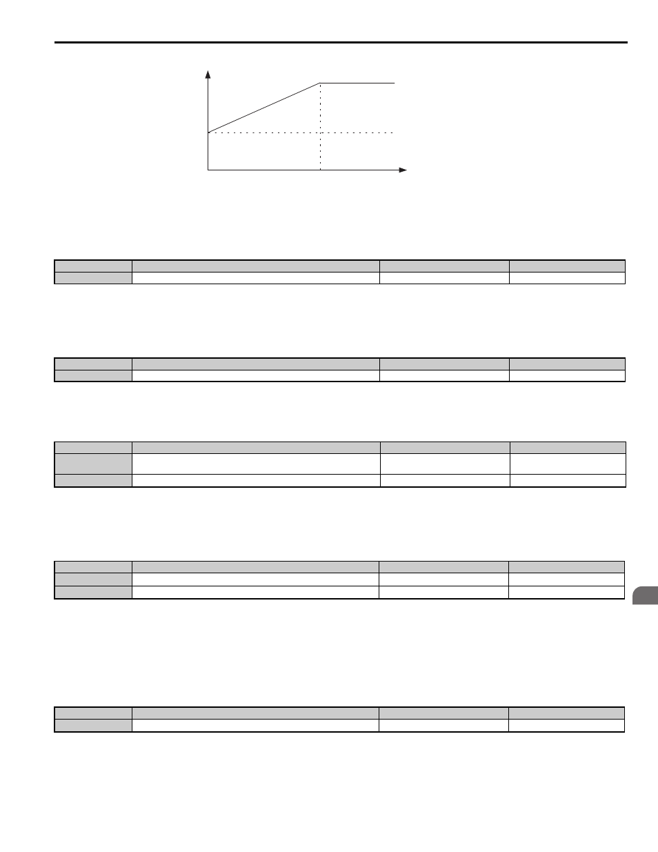
Figure 5.12
Figure 5.12 Settings at Low and High Speed during Deceleration (Leveling Speed is Selected)
■
C5-08: Speed Control Loop Integral Limit
Sets the upper limit for Speed Control Loop output as a percentage of the rated torque.
■
C5-16: Speed Control Loop Delay Time during Position Lock
Adjusts the delay applied to the torque reference output from Speed Control Loop during Position Lock. Increase this
setting gradually in increments of 0.01 when vibration is a problem. This parameter rarely needs to be changed.
■
C5-17, C5-18: Motor Inertia, Load Inertia Ratio
C5-17 and C5-18 determine the ratio of the machine inertia and the inertia of the motor being used.
■
C5-19, C5-20: Speed Control Loop P Gain Time, I Time during Position Lock
These parameters adjust the responsiveness of Speed Control Loop during Position Lock. Increase C5-19 and shorten C5-
20 if the motor rolls back immediately after the brake releases. Decrease C5-19 and lengthen C5-20 if vibrations occur.
■
C5-50: Set Vibrational Frequency
Sets the mechanical vibration filter frequency. Mechanical resonance may cause a humming sound or vibration while the
motor is running. A vibrational frequency filter can be used to suppress certain audible noise or vibration due to
mechanical resonance.
A setting of 0 will disable this parameter.
NOTICE: Test equipment may be required to determine the mechanical frequency. Setting C5-50 to an improper frequency will result in
ineffective filtering of the effects of mechanical resonance.
No.
Parameter Name
Setting Range
Default
C5-08
Speed Control Loop Integral Limit
0 to 400%
400%
No.
Parameter Name
Setting Range
Default
C5-16
Speed Control Loop Delay Time during Position Lock
0.000 to 0.500 s
0.000 s
No.
Parameter Name
Setting Range
Default
C5-17
Motor Inertia
0.0001 to 600.00 kgm
2
Determined by C6-01 and
o2-04
C5-18
Load Inertia Ratio
0.0 to 6000.0
1.0
No.
Parameter Name
Setting Range
Default
C5-19
Speed Control Loop Proportional Gain Time during Position Lock
0.00 to 300.00
Determined by A1-02
C5-20
Speed Control Loop Integral Time during Position Lock
0.000 to 10.000 s
0.100 s
No.
Parameter Name
Setting Range
Default
C5-50
Set Vibrational Frequency
0 Hz; 20 to 1000 Hz
0 Hz
P
,
I
Speed
P = C5-01
I = C5-02
P = C5-13
I = C5-14
C5-07
0
common
_