Cable length between drive and motor, Ground wiring, 7 main circuit wiring – Yaskawa L1000E AC Drive Technical Manual for CIMR-LE Models for Elevator Applications User Manual
Page 71
3.7 Main Circuit Wiring
YASKAWA ELECTRIC SIEP YAIL1E 01A YASKAWA AC Drive L1000E Technical Manual
71
El
ec
tr
ic
al
In
st
al
lat
io
n
3
NOTICE: Properly integrate auxiliary contacts into the control logic circuit to avoid unnecessary fault displays caused by contactors or
output switches placed between drive and motor. Improper installation of input and output contactors could result in damage to the
drive.
NOTICE: Before applying power to the drive, use power-off resistance checks to check for short-circuits between (R/L1, S/L2, and
T/L3) or between main circuit terminals and ground. Failure to comply may result in damage to the drive.
■
Cable Length Between Drive and Motor
Voltage drop along the motor cable may cause reduced motor torque when the wiring between the drive and the motor is
too long, especially at low frequency output. This can also be a problem when motors are connected in parallel with a
fairly long motor cable. Drive output current will increase as the leakage current from the cable increases. An increase in
leakage current may trigger an overcurrent situation and weaken the accuracy of the current detection.
Adjust the drive carrier frequency according to
Table 3.4
. If the motor wiring distance exceeds 100 m (328 ft.) because of
the system configuration, reduce the ground currents.
Refer to C6-03: Carrier Frequency on page 172
.
Table 3.4 Cable Length Between Drive and Motor
Note: When setting carrier frequency for drives running multiple motors, calculate cable length as the total wiring distance to all
connected motors.
■
Ground Wiring
Follow the precautions to wire the ground for one drive or a series of drives.
WARNING! Electrical Shock Hazard. Always use a ground wire that complies with technical standards on electrical equipment and
local installation regulations. Minimize the length of the ground wire. Improper equipment grounding may cause dangerous electrical
potentials on equipment chassis, which could result in death or serious injury.
WARNING! Electrical Shock Hazard. Be sure to ground the drive ground terminal (200 V class: Ground to 100
Ω or less, 400 V class:
Ground to 10
Ω or less). Improper equipment grounding may cause dangerous electrical potentials on equipment chassis, which could
result in death or serious injury.
NOTICE: Do not share the ground wire with other devices such as welding machines or large-current electrical equipment. Improper
equipment grounding could result in drive or equipment malfunction due to electrical interference.
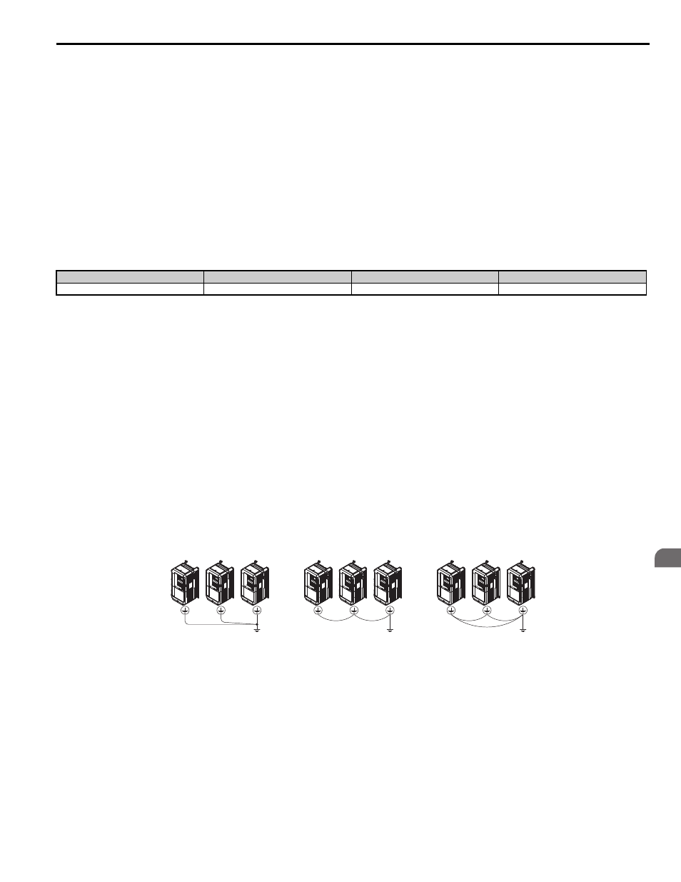
NOTICE: When using more than one drive, ground multiple drives according to instructions. Improper equipment grounding could
result in abnormal operation of drive or equipment.
Refer to
Figure 3.16
when using multiple drives. Do not loop the ground wire.
Figure 3.15
Figure 3.16 Multiple Drive Wiring
Cable Length
50 m (164 ft.) or less
100 m (328 ft.) or less
Greater than 100 m (328 ft.)
Carrier Frequency
15 kHz or less
5 kHz or less
2 kHz or less
OK
OK
Not OK