Comtech EF Data CRS-170A User Manual
Page 101
CRS-170A L-Band 1:1 Redundancy Switch
MN/CRS170A.IOM
Cables and Connections
Revision 13
5–31
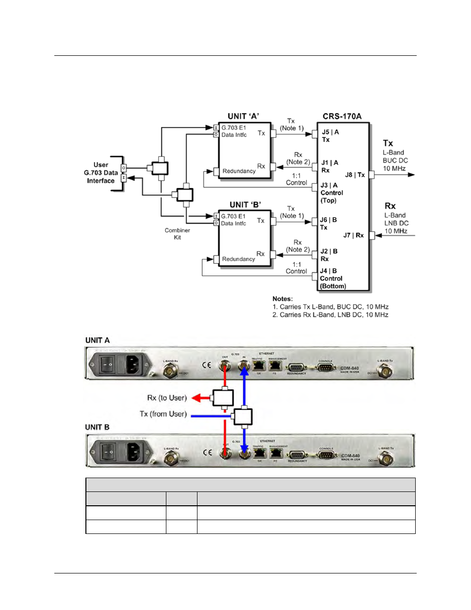
5.5.2.2 KT/12542 G.703 75Ω Data Interface Kit (for G.703 Unbalanced E1)
Figure 5-26 shows the block diagram and a cabling example for a CDM-840 1:1 configuration for
the G.703 Unbalanced E1 data interface. You must use the KT/12542 interface kit with the
CDM-840’s optional E1 Interface/RAN Optimization Hardware/FAST Feature upgrade.
CDM-840 Block Diagram – G.703 Unbalanced E1 Data Interface
KT/12542 G.703 75Ω Interface Cabling Kit (for G.703 Unbalanced E1 traffic)
CEFD Part No.
Qty
Description
CA/BNC75OHM
4
Cable – IF, BNC 75Ω, 1’
RF/SA32KC-IN/OUT
2
Combiner – 2-Way w/Bracket, 0.25-300 MHz, BNC 75Ω
Figure 5-26. CDM-840 Unbalanced G.703 E3/T375Ω Interface Kit – KT/12542