11 cabling the cdm-600l (clm-9600l), Ee figure 5-59 – Comtech EF Data CRS-170A User Manual
Page 143
CRS-170A L-Band 1:1 Redundancy Switch
MN/CRS170A.IOM
Cables and Connections
Revision 13
5–73
5.11 Cabling the CDM-600L (CLM-9600L)
1)
For information on configuring the CRS-170A L-Band 1:1 Redundancy Switch with
the CDM-600L (CLM-9600L) Open Network Satellite Modems for 1:1 operation,
see:
• Chapter 4. MODEM
AND
SWITCH
CONFIGURATION
• CLM-9600L Open Network Satellite Modem Installation and Operation Manual
(CEFD P/N MN/CLM9600L.IOM)
• CRS-150 1:1 Redundancy Switch Installation and Operation Manual
(CEFD P/N MN/CRS150.IOM)
2)
For information on the cables and cable assemblies specified in this section, see
Appendix A. CABLE DRAWINGS.
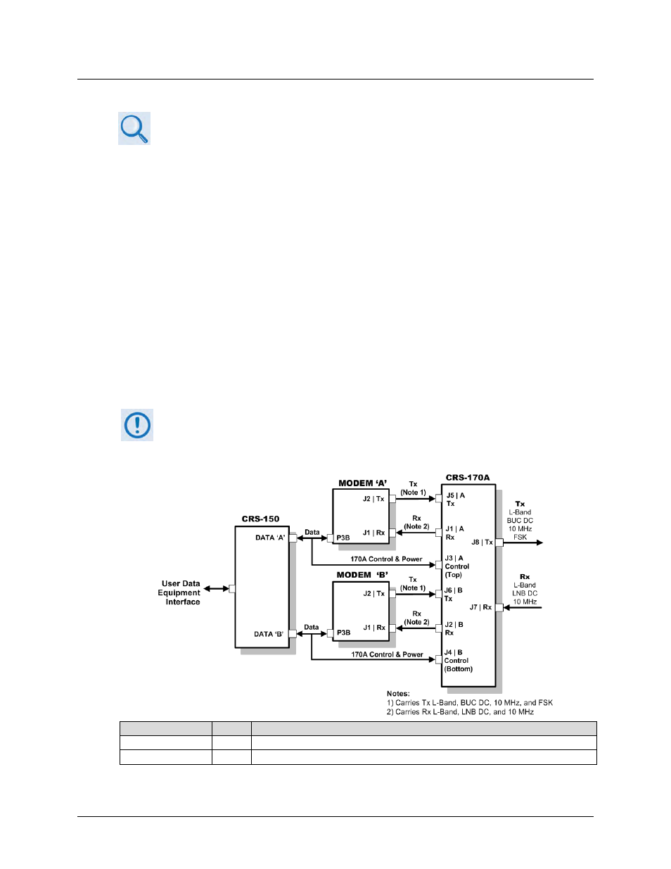
Figure 5-59 shows the block diagram for connecting a pair of CDM-600L (CLM-9600L) Open
Network Satellite Modems together with the CRS-150 and CRS-170A switches. This figure also
provides a table that identifies the cable assemblies that may be supplied with the CRS-170A in
this configuration.
When you connect the Control Interface cables between the CRS-170A, the
CRS-150, and the modems, make sure that you securely fasten the screw locks on
the Type ‘D’ connectors. This prevents accidental disconnection of the cables,
particularly when you are removing and replacing a standby unit.
CEFD Part No.
Qty
Description
CA/WR10456-4
2
Cable – 1:1 Y-Splitter, Data/Control, DB-25M DB-25M, 4’ / DB-9M, 1’
CA/RF10453-4
4
RoHS-Compliant Cable – IF (Tx/Rx), 50Ω Type ‘N’, 4’
Figure 5-59. CDM-600L (CLM-9600L) Block Diagram – Cable Connections