Comtech EF Data CRS-170A User Manual
Page 29
CRS-170A L-Band 1:1 Redundancy Switch
MN/CRS170A.IOM
Introduction
Revision 13
1–9
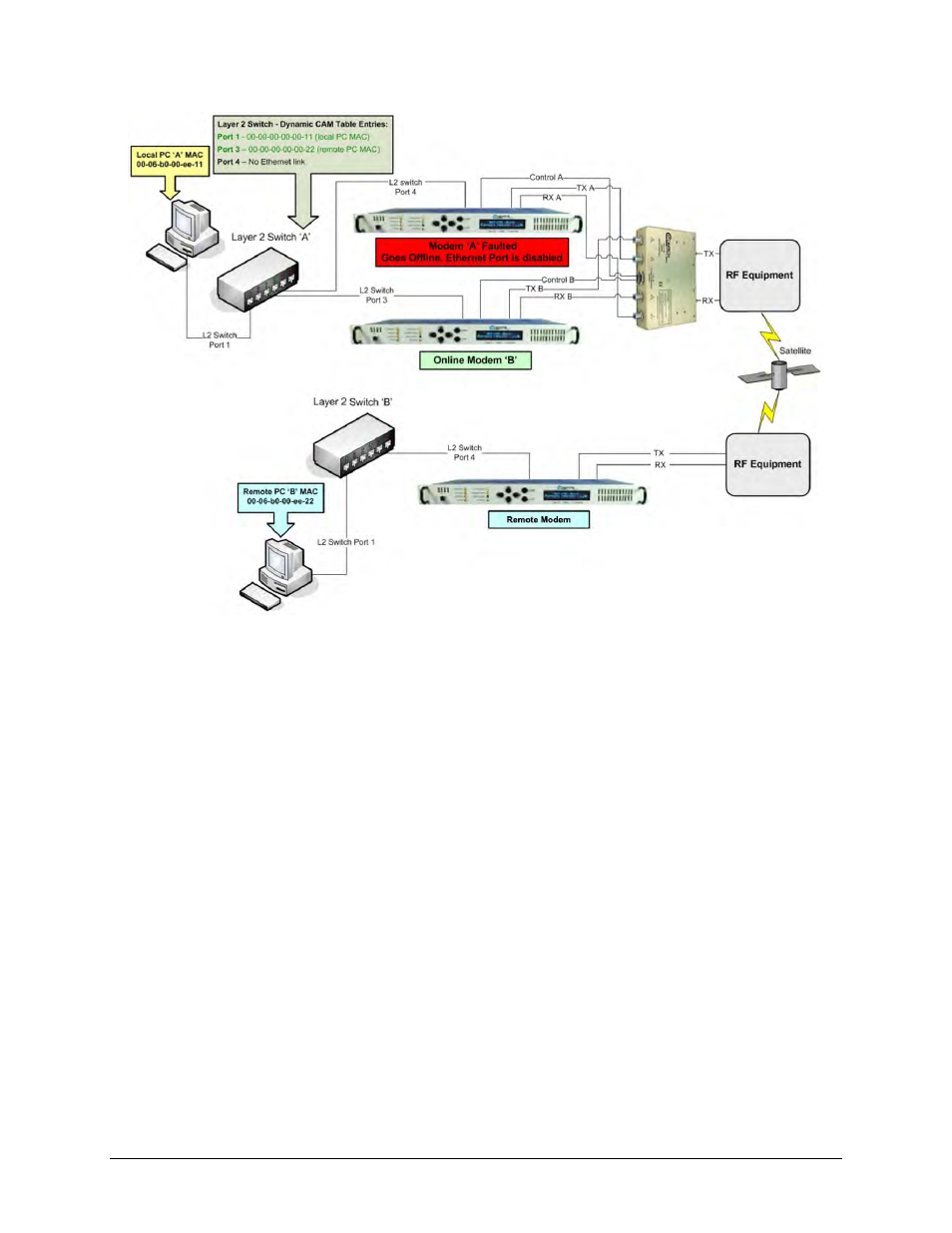
Figure 1-5. CDM-625/A, -850, -840, -760, -750, -710GL, -710, -700 1:1 IP Redundancy
Managed Switch Mode – Switchover
As shown in Figure 1-5, in the event of a fault on the Online unit ‘A’, the following will occur:
• Modem ‘A’ goes offline and disables its Ethernet data interface.
• Simultaneously, Modem ‘B’ goes online and enables its Ethernet data interface.
• Layer 2 Switch ‘A’ senses that Port 4 is no longer active and clears the CAM table entries for
that port.
• When the next Ethernet packet from Local PC ‘A’ destined for Remote PC ‘B’ arrives at
Switch ‘A’, there is no CAM entry for the PC ‘B’ MAC, so it will be broadcast to all active
ports.
• When the next Ethernet packet from Remote PC ‘B’ arrives at Switch ‘A’, Switch ‘A’
dynamically adds the PC ‘B’ MAC to the CAM table for Port 3.
Note the following:
1)
The Managed Switch Mode method of redundancy is intended to be equivalent to pulling
the Ethernet cable from one port and putting it into a different port on the same switch.