Comtech EF Data CRS-170A User Manual
Page 138
CRS-170A L-Band 1:1 Redundancy Switch
MN/CRS170A.IOM
Cables and Connections
Revision 13
5–68
5.10.2 Modem-to-User Data Interface Kit and Connection Examples
In addition to the basic Modem-to-Switch cabling shown previously, a number of data interface
configuration kits are available for use with the CDM-700 Satellite Modem. Separate cabling kits
are needed for these data interfaces.
The data interface combinations allowable in the CDM-700 chassis Interface Slots
1 and 2 are as follows:
Interface Slot 1
Interface Slot 2
Dual G.703 (CDI-10)
None
Dual G.703 (CDI-10)
HSSI (CDI-60)
GigE (CDI-70)
OC3 Optical (CDI-50-1) Single Mode
None
155MB Copper (CDI-50-1)
HSSI (CDI-60)
None
HSSI (CDI-60
GigE (CDI-70)
GigE (CDI-70)
None
GigE (CDI-70)
None
Dual G.703 (CDI-10)
HSSI (CDI-60)
GigE (CDI-70)
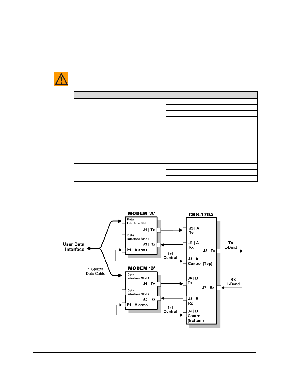
5.10.2.1 Modem-to-User Non-IP Data Interface Kit and Connection
Examples
Figure 5-54. CDM-700 Block Diagram – UserModemSwitchTraffic