Comtech EF Data CRS-170A User Manual
Page 38
CRS-170A L-Band 1:1 Redundancy Switch
MN/CRS170A.IOM
Introduction
Revision 13
1–18
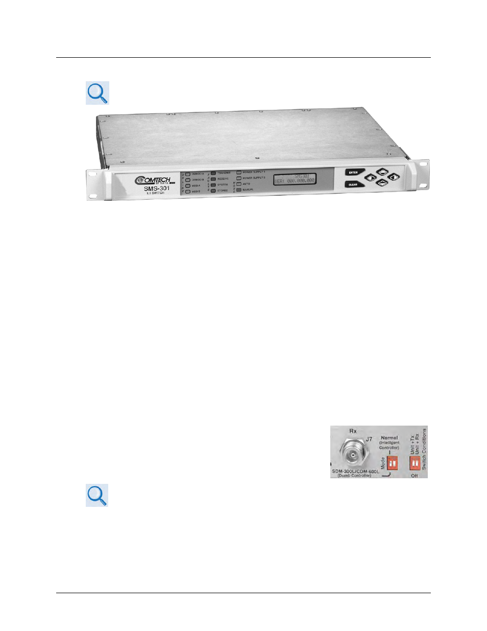
1.3.3.2 Operation with SDM-300L3 Modems and SMS-301 Switch
SMS-301 Redundancy Switch Installation and Operation Manual (CEFD P/N
MN/SMS301.IOM)
Figure 1-11. Comtech EF Data SMS-301 1:1 Redundancy Switch
The SMS-301 1:1 Redundancy Switch (
) is modified from the standard version that
operates with 70/140 MHz IF SDM-300A modems. All operation as a 70/140 MHz modem switch
applies except that the RF switching is done in the CRS-170A. The BNC IF connectors are
replaced by Type ‘N’ connectors, as BNC connectors and internal switching are not suitable for
L-Band operation. Signals on the ‘J14 | Status/Faults’ connector are modified to provide +12VDC
power output and A/B switch control outputs to the CRS-170A. The SMS-301 has its own
redundant power supplies, so the CRS-170A receives redundant power.
Operation here is similar to operation of the CRS-150 1:1 Redundancy Switch with CDM-600L
(CLM-9600L) Online and Backup modems. The SMS-301 operates as the principal switch and
controller, with the CRS-170A providing the required switching for L-Band signals, references,
and power supplies that the SMS-301 cannot handle.
The SMS-301 connects to the Online and Backup SDM-300L3 modems, monitors the fault status
of these two units, and controls the routing of data to and from the units. IF signals, 10MHz
reference signals, DC power for the BUC and LNB, and FSK signaling to the BUC are switched in
the CRS-170A under control of the SMS-301. In the case of equipment failure, automatic
switching takes place to protect the traffic circuit.
Set the DIP switches on the CRS-170A antenna side to establish
modem-specific operation. For the SDM-300L3, place the Mode
switch in the SDM-300L/CDM-600L (Dumb Controller) position
and push the Switch Condition switches to the OFF position.
Sect. 4.9 Configure Switch DIP Settings