9 crs-170a switch dip settings – Comtech EF Data CRS-170A User Manual
Page 69
CRS-170A L-Band 1:1 Redundancy Switch
MN/CRS170A.IOM
Modem and Switch Configuration
Revision 13
4–21
4.9 CRS-170A Switch DIP Settings
The ‘Switch Conditions’ DIP switches are set depending upon the type of Tx or Rx
traffic conditions resultant of switchover. Some modems have additional settings or
alarm masks that affect conditions – see your individual modem manual for detailed
explanations.
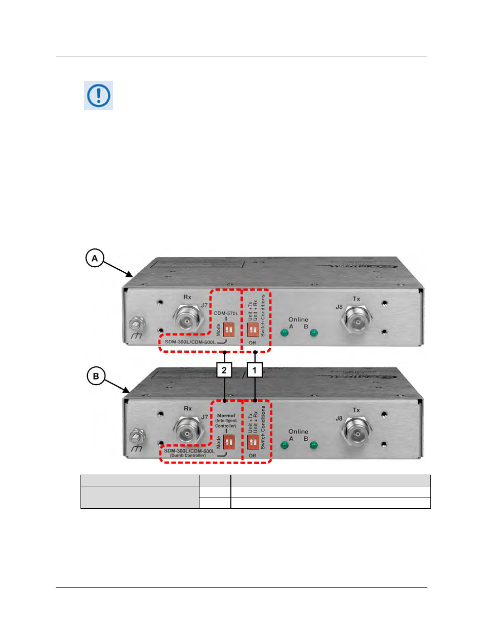
Figure 4-4 shows the DIP switches provided on the Antenna Side of the CRS-170A L-Band 1:1
Redundancy Switch (towards the BUC and LNB). Use these features to set the ‘Mode’ and
‘Switch Conditions’.
Note that the ‘Mode’ DIP switch labeling differs between the original and current (i.e., Rev. ‘A’
and later) versions of the CRS-170A.
On the next page, Table 4-1 details the settings for the ‘Mode’ DIP switch set on a per-modem
basis, and the ‘Switch Conditions’ DIP switch settings that determine switchover functionality
for a given redundancy configuration.
Switch Version
Item Description
A – Original Chassis Design
B – Rev ‘A’ and LATER Design
1
“Switch Conditions” DIP Switches
2
“Mode Settings” DIP Switches
Figure 4-4. CRS-170A Antenna Side – DIP Switches