1 modem-to-switch control interface connection, Figure 5-52 – Comtech EF Data CRS-170A User Manual
Page 136
CRS-170A L-Band 1:1 Redundancy Switch
MN/CRS170A.IOM
Cables and Connections
Revision 13
5–66
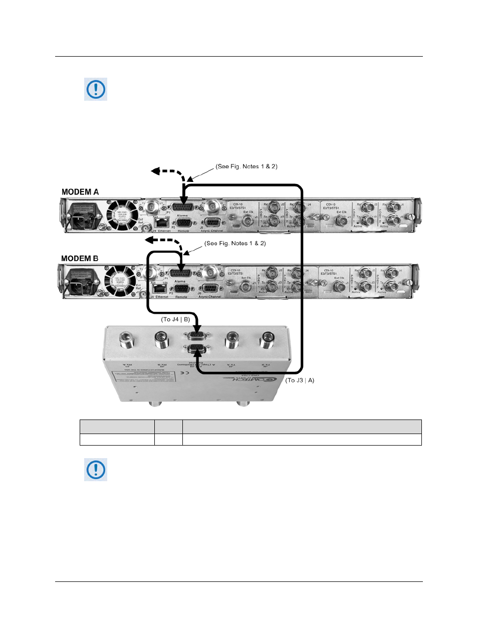
5.10.1.1 Modem-to-Switch Control Interface Connection
1)
Excluding the modems, the KT/12551 CRS-170A L-Band 1:1 Redundancy Kit
(Sect. 5.2.2) provides all components shown in Figure 5-52.
2)
When you connect the Control Interface cables between the CRS-170A and the
modems, make sure that you securely fasten the screw locks on the Type ‘D’
connectors. This prevents accidental disconnection of the cables, particularly
when you are removing and replacing a standby unit.
CEFD Part No.
Qty
Description
CA/WR12135-1
See Notes
2
Control Cable – Universal, DB-9M, 4’
FIGURE NOTES:
1)
To provide user access to the modem “Fault Summary Relay,” Control ‘Y’ Cable
(CEFD P/N CA/WR13011-4), sold separately, is available for use in place of the
CA/WR12135-1 Control Cable.
2)
The CA/WR12135-1 Control Cable will mute the Offline modem’s Tx IF. If this is
not desired, then an alternate Control Cable (CEFD P/N CA-0000187), sold
separately, is available for use instead.
Figure 5-52. CDM-700 Modem-to-Switch Control Connections