2 j3 | control connector (top) – modem ‘a’ (db-9f) – Comtech EF Data CRS-170A User Manual
Page 47
CRS-170A L-Band 1:1 Redundancy Switch
MN/CRS170A.IOM
Switch Connectors and Pinouts
Revision 13
3–5
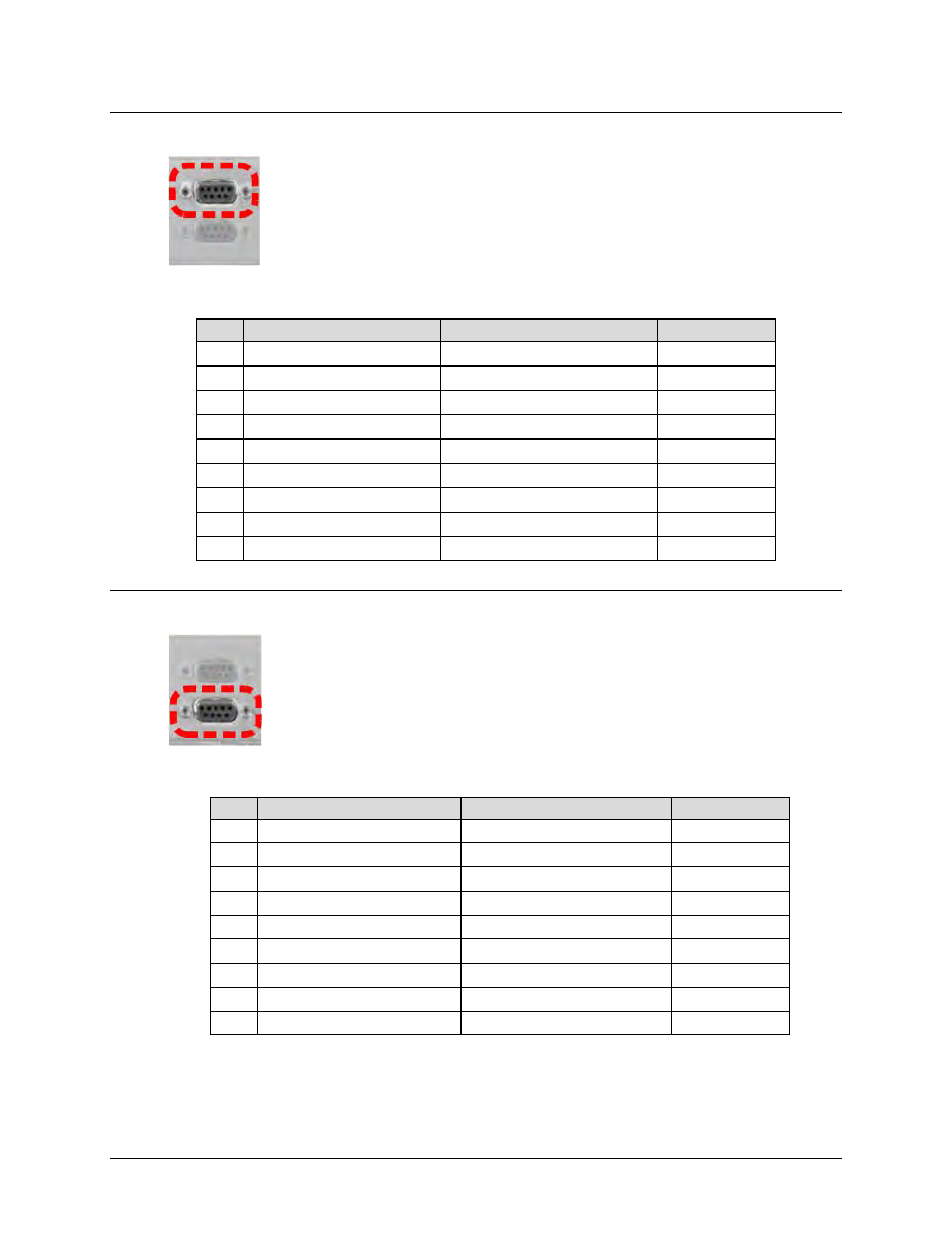
3.2.1.2 J3 | Control Connector (Top) – Modem ‘A’ (DB-9F)
The Modem ‘A’ Control connector is a 9-pin Type ‘D’ female interface. Pins 2, 3,
and 4 carry signals looped through the switch module from Modem ‘B’ to
Modem ‘A’, while pins 6, 7, and 8 loop the same signals from Modem ‘A’
through to Modem ‘B’. The 12VDC input, which is diode OR’ed with the
corresponding 12VDC input from Modem ‘B’, powers the switch module.
Table 3-2. J3 | Control A Modem Connector Pinouts
Pin Signal Name
Signal Function
Direction
5
Ground
Signal Ground
---
9
+12VDC
+12 VDC
In
4
ONLINE_A
Modem ‘A’ Online
Out
8
SERIAL_FAULT_A
Modem ‘A’ Serial Faults
In
3
CLK_OUT_B
Modem ‘B’ Clk Out
Out
7
CLK_IN_A
Modem ‘A’ Clk In
In
2
AUX_SER_TX_B
Modem ‘B’ Tx Comms
Out
6
AUX_SER_TX_A
Modem ‘A’ Tx Comms
In
1
Ground
Signal Ground
---
3.2.1.3 J4 | Control Connector (Bottom) – Modem ‘B’ (DB-9F)
The Modem ‘B’ Control connector is a 9-pin Type ‘D’ female interface. Pins 2, 3,
and 4 carry signals looped through the switch module from Modem ‘A’ to
Modem ‘B’, while pins 6, 7, and 8 loop the same signals from Modem ‘B’
through to Modem ‘A’. The 12VDC input, which is diode OR’ed with the
corresponding 12 VDC input from Modem ‘A’, powers the switch module.
Table 3-3. J4 | Control B Modem Connector Pinouts
Pin Signal Name
Signal Function
Direction
5
Ground
Signal Ground
---
9
+12VDC
+12VDC
In
4
ONLINE_B
Modem ‘B’ Online
Out
8
SERIAL_FAULT_B
Modem ‘B’ Serial Faults
In
3
CLK_OUT_A
Modem ‘A’ Clk Out
Out
7
CLK_IN_B
Modem ‘B’ Clk In
In
2
AUX_SER_TX_A
Modem ‘A’ Tx Comm
Out
6
AUX_SER_TX_B
Modem ‘B’ Tx Comm
In
1
Ground
Signal Ground
---