2 modem-to-switch if interface connection, Figure 5-47 – Comtech EF Data CRS-170A User Manual
Page 129
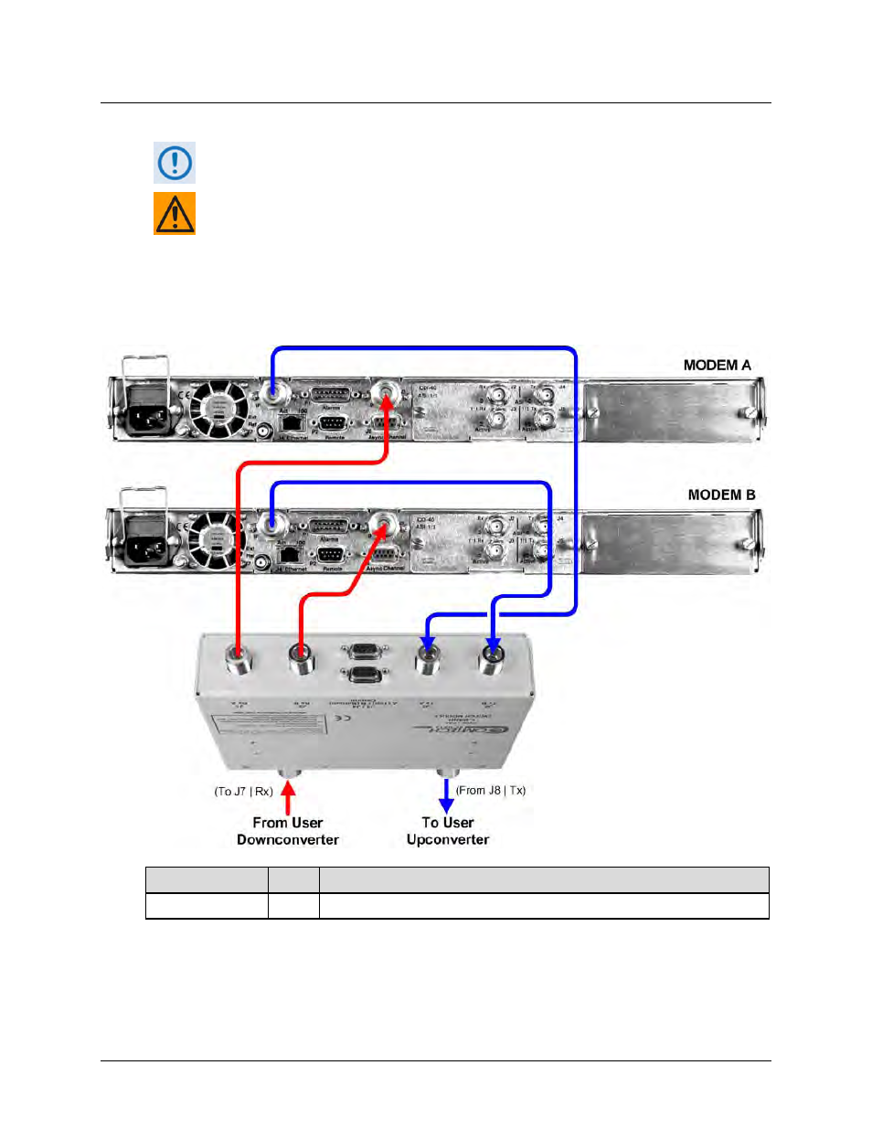
CRS-170A L-Band 1:1 Redundancy Switch
MN/CRS170A.IOM
Cables and Connections
Revision 13
5–59
5.9.1.2 Modem-to-Switch IF Interface Connection
Excluding the modems, the KT/12551 CRS-170A L-Band 1:1 Redundancy Kit (Sect.
5.2.2) provides all components shown in Figure 5-47.
EXAMPLE: The Tx IF from ‘MODEM A’ connects to the Tx IF port ‘J5 | Tx A’ on the
CRS-170A; similarly, the Tx IF from ‘MODEM B’ connects to the Tx IF port ‘J6 | Tx B’
on the CRS-170A.
The same logic applies for the Rx IF connections. It is important to note that failure
to observe this requirement will result in system malfunction.
CEFD Part No.
Qty
Description
CA/RF10453-4
4
RoHS-Compliant Cable – IF (Tx/Rx), 50Ω Type ‘N’, 4’
Figure 5-47. CDM-710 Modem-to-Switch L-Band IF Connections