2 modem-to-switch if interface connection, Figure 5-2 – Comtech EF Data CRS-170A User Manual
Page 77
CRS-170A L-Band 1:1 Redundancy Switch
MN/CRS170A.IOM
Cables and Connections
Revision 13
5–7
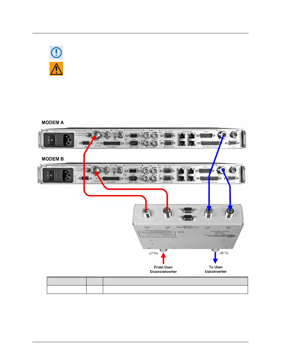
5.3.1.2 Modem-to-Switch IF Interface Connection
Excluding modems, the KT-0000160 CRS-170A L-Band 1:1 Redundancy Kit (Sect.
5.2.1) provides all components shown in Figure 5-2.
EXAMPLE: The Tx IF from ‘MODEM A’ connects to the Tx IF port ‘J5 | Tx A’ on the
CRS-170A; similarly, the Tx IF from ‘MODEM B’ connects to the Tx IF port ‘J6 | Tx B’
on the CRS-170A.
The same logic applies for the Rx IF connections. It is important to note that failure
to observe this requirement will result in system malfunction.
5.3.1.2.1 Modem-to-Switch L-Band (Rx/Tx) IF Interface Connection
CEFD Part No.
Qty
Description
CA/RF10453-4
4
RoHS-Compliant Cable – IF (Tx/Rx), 50Ω Type ‘N’, 4’
Figure 5-2. CDM-625/A Modem-to-Switch L-Band IF Connections