1 modem-to-switch control interface connection, Figure 5-1 – Comtech EF Data CRS-170A User Manual
Page 76
Advertising
CRS-170A L-Band 1:1 Redundancy Switch
MN/CRS170A.IOM
Cables and Connections
Revision 13
5–6
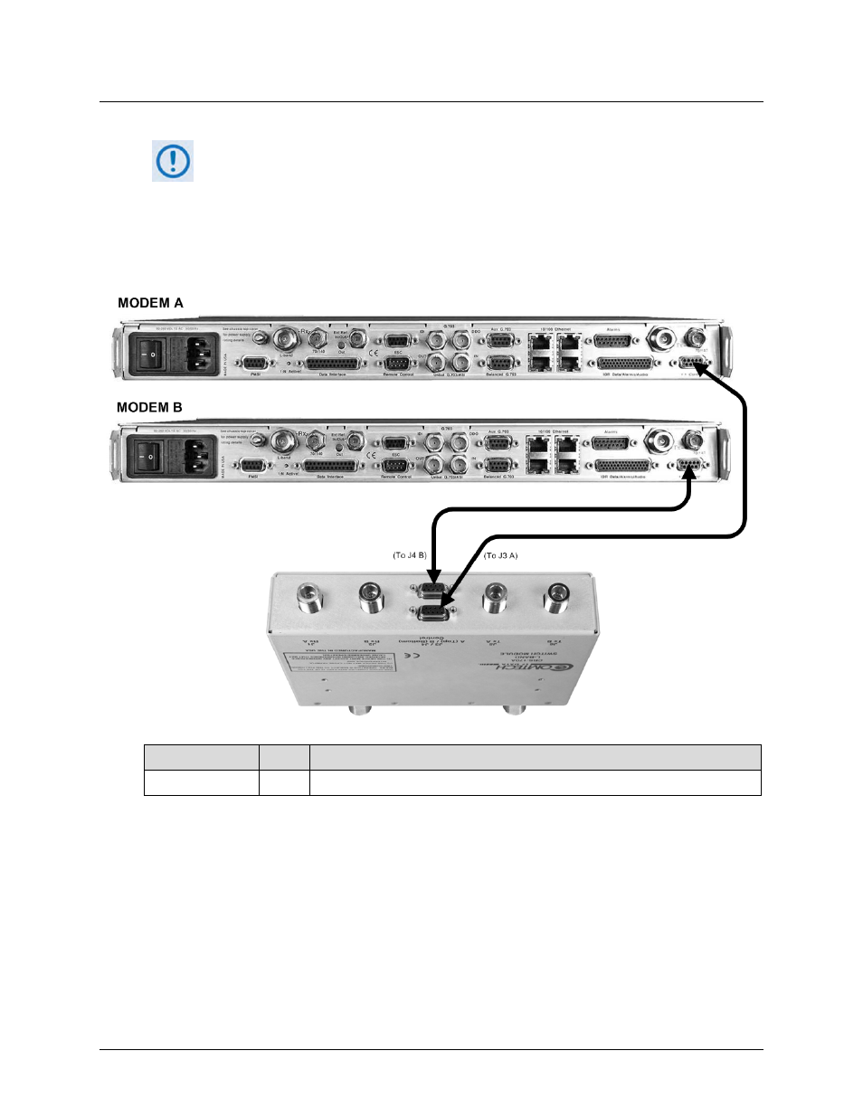
5.3.1.1 Modem-to-Switch Control Interface Connection
1)
Excluding modems, the KT-0000160 CRS-170A L-Band 1:1 Redundancy Kit (Sect.
5.2.1) provides all components shown in Figure 5-1.
2)
When you connect the Control Interface cables between the CRS-170A and the
modems, make sure that you securely fasten the screw locks on the Type ‘D’
connectors. This prevents accidental disconnection of the cables, particularly
when you are removing and replacing a standby unit.
CEFD Part No.
Qty
Description
CA/WR9378-4
2
Control Cable – Universal, DB-9M, 4’
Figure 5-1. CDM-625/A Modem-to-Switch Control Connections
Advertising