Comtech EF Data CRS-170A User Manual
Page 114
CRS-170A L-Band 1:1 Redundancy Switch
MN/CRS170A.IOM
Cables and Connections
Revision 13
5–44
5.7.1.3 Modem-to-User Data Interface Connections and Examples
In addition to the control and IF Modem-to-Switch cabling shown previously, a number of data
interface configurations are available for the CDM-570L/AL.
5.7.1.3.1 Modem-to-User Non-IP Data Interface Connections and Examples
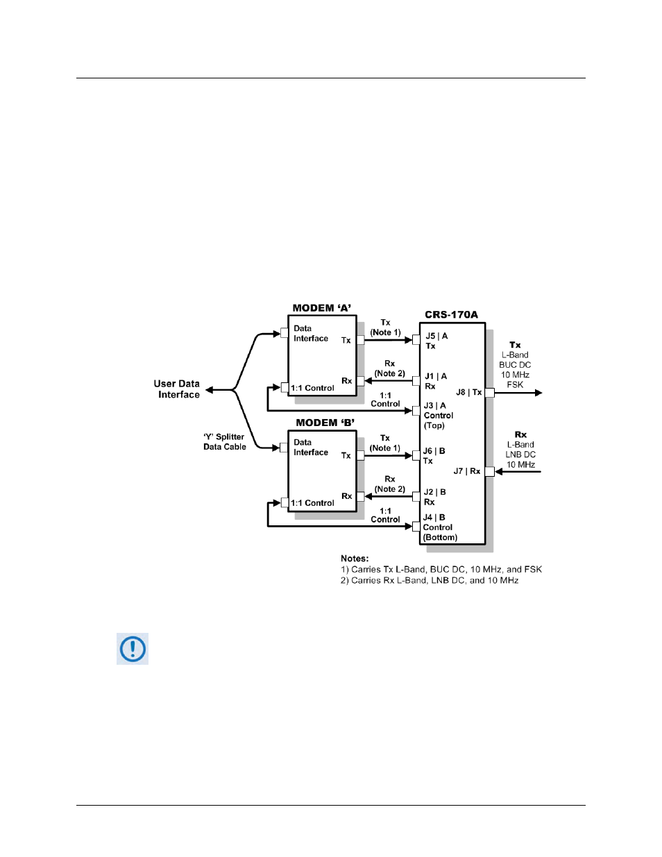
The block diagram shown in Figure 5-35 is typical for the examples shown in Sects. 5.7.1.3.1.1
through 5.7.1.3.1.3.
With the exception of the CDM-570L ONLY IP (10/100 Ethernet) Interface configuration shown
in Sect. 5.7.1.3.1.4, where you must use user-provided Ethernet cables and hub, you will need
one cable and component set per 1:1 modem pair for each user interface (see examples for
specific quantities).
Figure 5-35. CDM-570L/AL Block Diagram – UserModemSwitchTraffic
Unless otherwise specified, the interface cables and components identified in each of
the examples that follow are provided in the KT/10860-1 1:1 Redundancy Kit (see Sect.