2 physical features, 1 modem side features, 2 physical features 1.2.1 modem side features – Comtech EF Data CRS-170A User Manual
Page 23
CRS-170A L-Band 1:1 Redundancy Switch
MN/CRS170A.IOM
Introduction
Revision 13
1–3
1.2 Physical Features
1.2.1 Modem Side Features
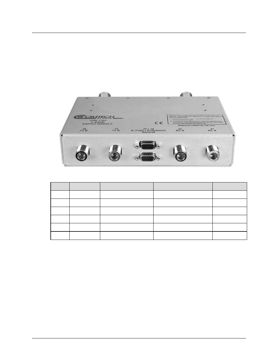
Figure 1-2 shows the modem side of the CRS-170A. The connectors provided here facilitate all
necessary external connections between the CRS-170A and the compatible Comtech EF Data
modems.
J6 TX B
J5 TX A
J3 Control A
J4 Control B
J2 RX B
J1 RX A
Ref Des Name
Connector Type
Function
Chapter Sect.
J1
Rx A
Type ‘N’
Input to Modem ‘A’
3.2.1.1
J2
Rx B
Type ‘N’
Input to Modem ‘B’
3.2.1.1
J3
Control A
DB-9F 9-pin Type ‘D’ female Modem ‘A’ Control Interface
3.2.1.2
J4
Control B
DB-9F 9-pin Type ‘D’ female Modem ‘B’ Control Interface
3.2.1.3
J5
Tx A
Type ‘N’
Output from Modem ‘A’
3.2.1.1
J6
Tx B
Type ‘N’
Output from Modem ‘B’
3.2.1.1
Figure 1-2. CRS-170A – Modem Side Connectors