2 top and antenna side features – Comtech EF Data CRS-170A User Manual
Page 24
Advertising
CRS-170A L-Band 1:1 Redundancy Switch
MN/CRS170A.IOM
Introduction
Revision 13
1–4
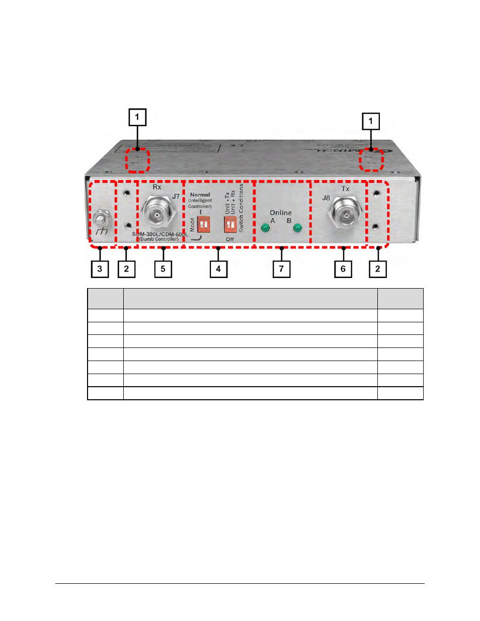
1.2.2 Top and Antenna Side Features
Figure 1-3 shows the CRS-170A top and antenna side features and the chapters that provide
more detailed information.
Feature Description
Chapter
Sect.
1
4X #6-32 holes for vertical rack mounting (used with Switch Mounting Kit KT/11708)
2.2
2
4X #6-32 holes for horizontal rack mounting (used with Switch Mounting Kit KT/11708)
2.2
3
Ground Stud
2.2, 3.2.2.2
4
“Switch Conditions” DIP Switches
1.3.1, 4.9
5
J7 | Rx Type ‘N’ Input Connector
3.2.2.1
6
J8 | Tx Type ‘N’ Output Connector
3.2.2.1
7
Online LED Indicators
1.3.1
Figure 1-3. CRS-170A – Top and Antenna Side Features
Advertising