Operation – Hypertherm HT4001 Plasma Arc Cutting System User Manual
Page 105
OPERATION
6-98
5-14
HT4001
Instruction Manual
Note:
If using the H-401 power supply as a slave, note that the current control adjust knob on the
front panel of the H-401 will have no effect on setting current for the slave.
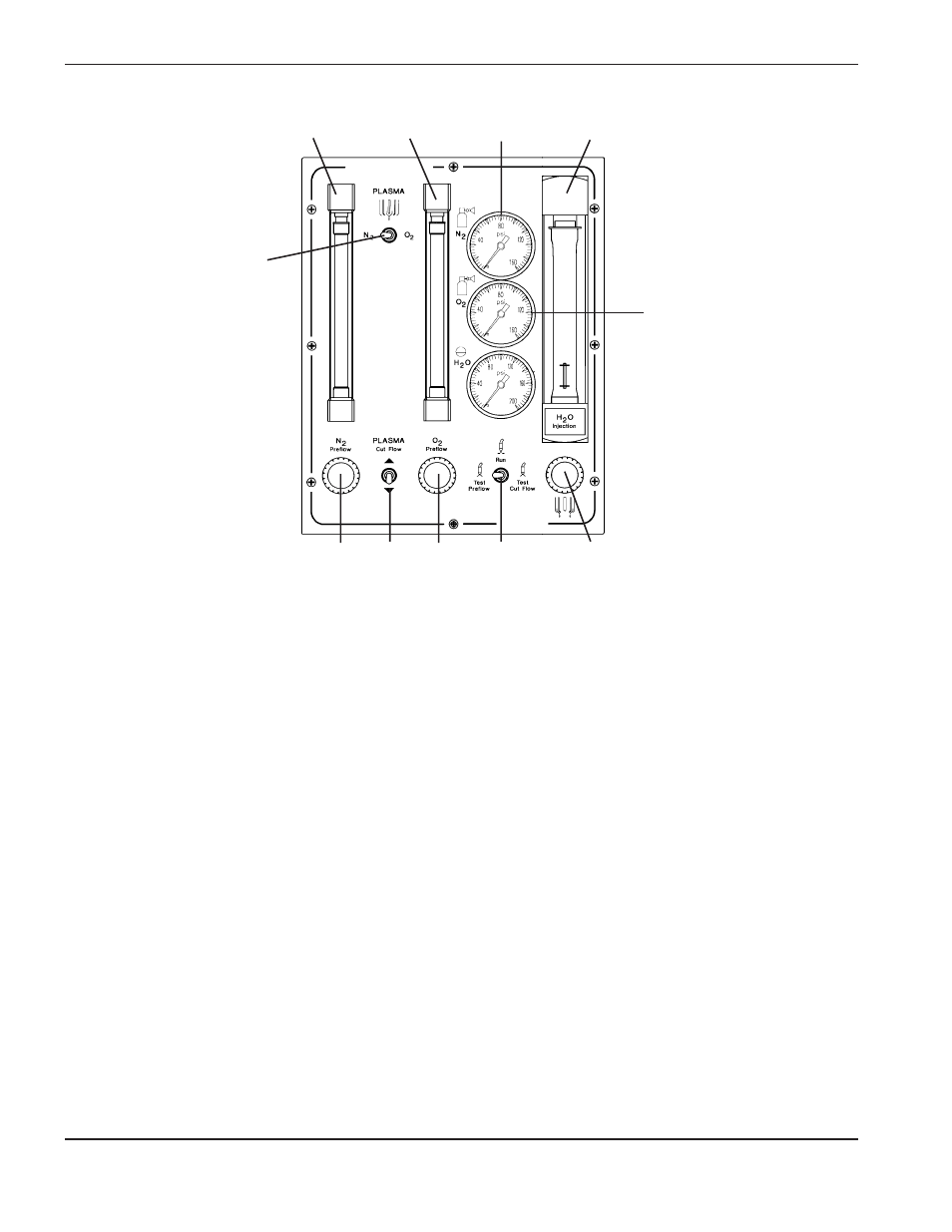
11. Set the S2 toggle switch to Test Preflow. Set the preflow flow rate(s) on the O
2
and/or N
2
flow meters using the
MV2 and/or MV3 metering valve(s). Select the test preflow rates from the Cut Charts.
Note:
If the power supply has been off for more than one hour, or if you have changed
consumable parts or have changed gases, purge gas lines by leaving system in
TEST PREFLOW for one minute.
12. Set S2 to Test Cut Flow. Set the cut flow rate on the O
2
or N
2
flow meters using the MV1 metering valve
(momentary switch). Select the test cut flow rates from the Cut Charts.
Note:
If the power supply has been off for more than one hour, or if you have changed
consumable parts or have changed gases, purge gas lines by leaving system in
TEST PREFLOW for one minute.
13. Check the water flow rate at the water flow meter and adjust with MV4 metering valve, if necessary. See the
Cut Charts for water flow rates.
14. Verify that there is a uniform conical water pattern at the front of the torch. If the pattern is irregular, shut the
power supply down at the main disconnect switch and check the nozzle and swirl ring. Replace with new parts,
if worn or damaged.
15. Set S2 to Run. The system is now ready for operation.
N
2
Flow
meter
S1
MV2 MV1
MV3
S2
MV4
O
2
Flow
meter
N
2
Press.
Gauge
Water Flow
meter
O
2
Press.
Gauge
Figure 5-9
Gas Console Reference – Daily Startup