System units placement -4, System units placement, Installation – Hypertherm HT4001 Plasma Arc Cutting System User Manual
Page 57: Ht4001
INSTALLATION
11-97
4-4
HT4001
Instruction Manual
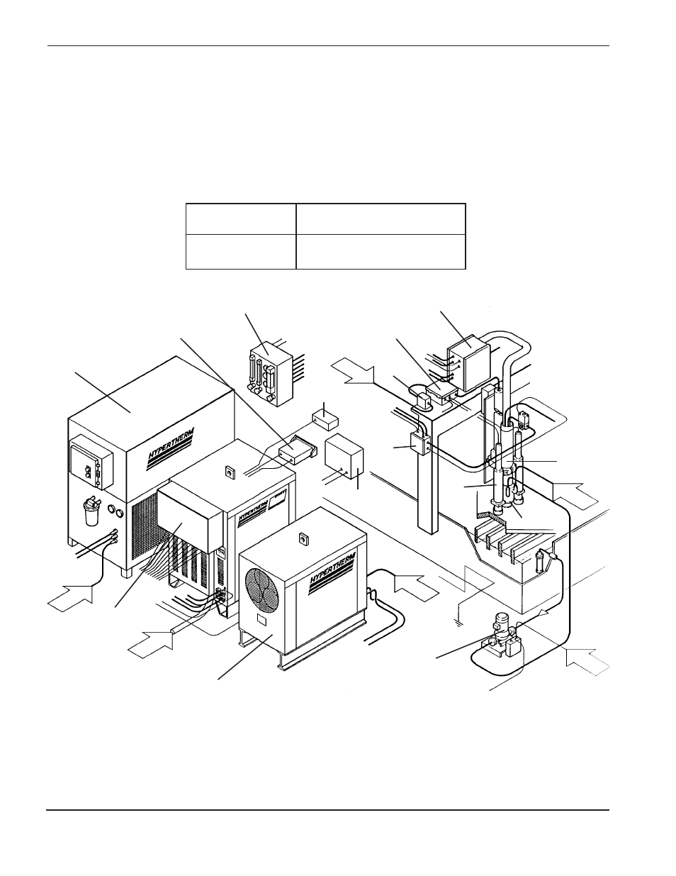
System Units Placement
• Position all required units prior to making electrical, gas, and interface connections.
• See Section 2 for mounting dimensions of all units.
• Ground all external modules in the HT4001 system to earth.
• To prevent leaks in the system, tighten all gas and water connections to the following specifications:
* System shown includes H401 slave, IHS, and water muffler options
Air
Air
Torch
Machine
Interface
Motor
Valve
Console
Water
Muffler
IHS
Probe
Air
Regulator
Gas Console (mount near operator)
RHF Console
IHS Console
Timer/Counter
Water
Chiller
HT4001
Remote V/C Control
(mount near operator)
Water
Power
H401
Slave
(optional)
Water Muffler
Pump
Power
Power
Figure 4-2
Typical HT4001 System* Component Placement for Gantry Cutter
Gas or water
Torch Specification
hose size
lbf-in
lbf-ft
kgf-cm
Up to 3/8" (9.5 mm)
75-85
6.25-7
86-98
1/2" (12.7 mm)
360-480
30-40
415-550