Ht4001 interconnection reference map -5, Ht4001 interconnection reference map – Hypertherm HT4001 Plasma Arc Cutting System User Manual
Page 58
Advertising
H
2
O
in
20
IHS
Console
Machine
Computer
Interface
INSTALLATION
HT4001
Instruction Manual
4-5
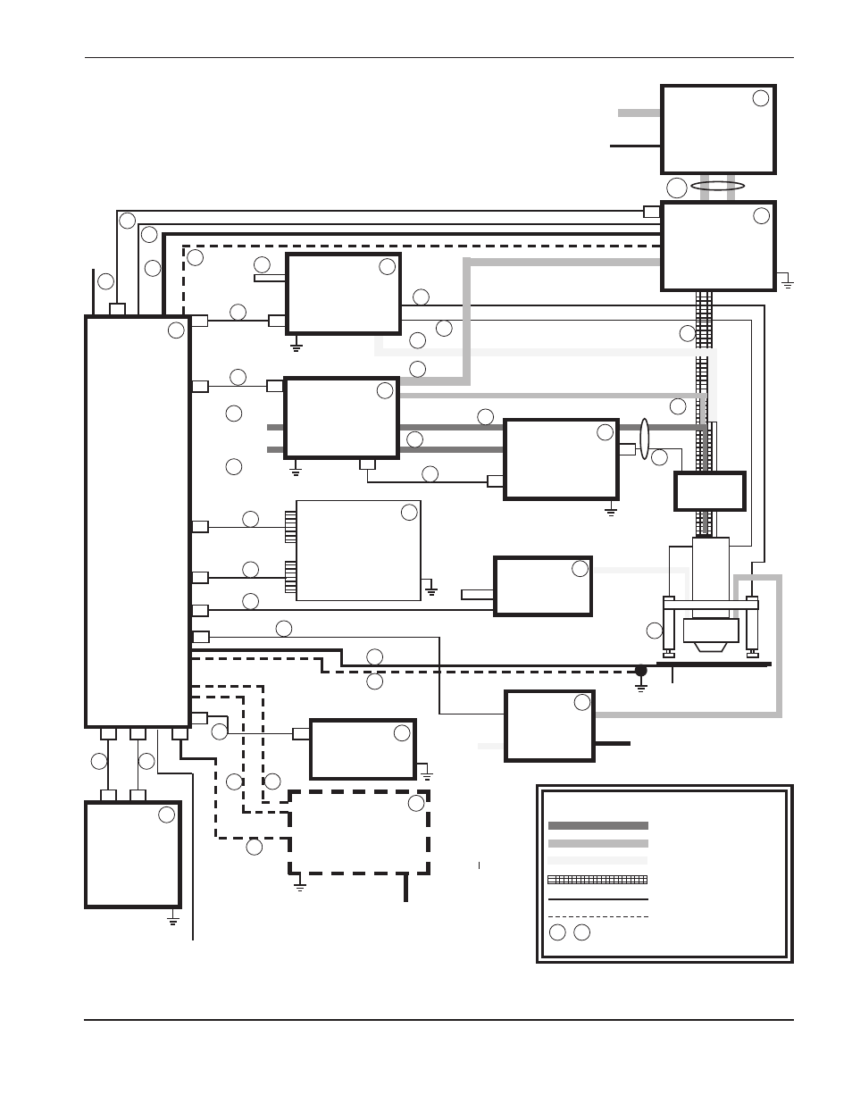
HT4001 Interconnection
Reference Map
Figure 4-3
HT4001 Interconnect System Diagram with IHS, Water Muffler and Slave
Key
Plasma gas hose
Water hose
Air hose
Shielded torch leads
Cables
Slave requirements
Reference to
installation steps
RHF
Console
HT4001
Power
Supply
400 Amp
Remote
V/C
Timer/
Counter
H401 or H601
Slave
W-M
Air Control
Work table
Air in
H
2
O in
N
2
in
3-Phase
Power
To Second
HT4001 System
H
2
O
in
3-Phase
Power
Water
Chiller
15
5
4
2
1
34
25
24
17
27
Motor
Valve
Console
28
28
26
J
B
3-Phase
Power
W-M
Supply
K
Air in
K
L
13
14
33
8
7
3
23
22
21
16
D
Gas
Console
C
18
19
6
12
F
A
G
H
3-Phase
Power
10
30
31
32
11
9
E
, etc.
19
5
Off Valve
Advertising