Relay board pcb4 status indicators -24, Relay board pcb4 status indicators, Maintenance – Hypertherm HT4001 Plasma Arc Cutting System User Manual
Page 150
MAINTENANCE
6-98
6-24
HT4001
Instruction Manual
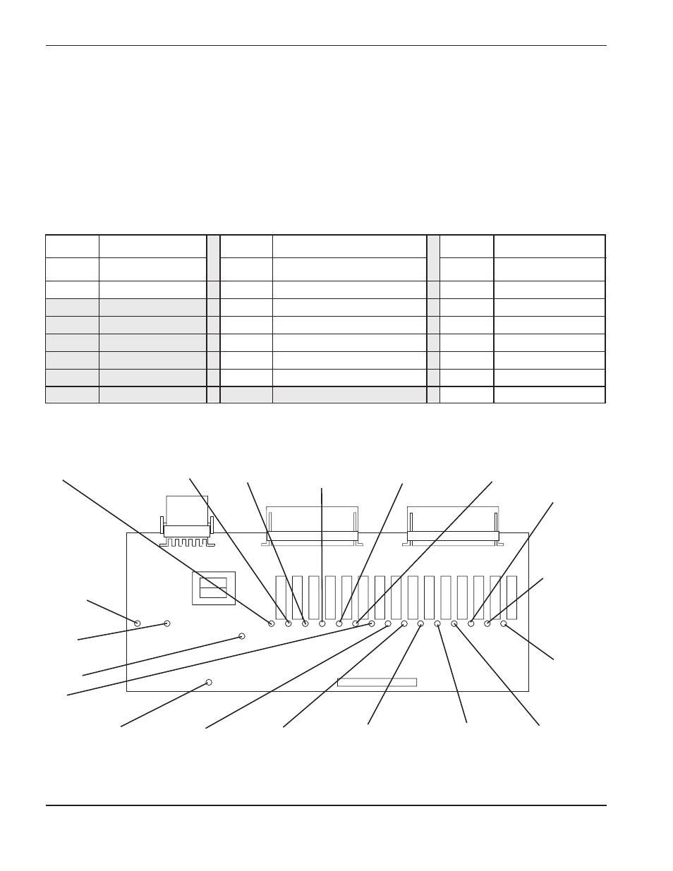
Relay Board PCB4 Status Indicators
Relay board PCB4 interfaces certain controls in the power supply, gas console, RHF console, and motor valve
console to the control board (PCB2). The control board sends a command to the relay board, and the relay board
responds by sending 120VAC to the control (and also lighting an LED on the relay board). The control board also
tells the relay board to shut off the 120VAC to the particular control (which shuts off the LED). LEDs are located
adjacent to the relay that switches the 120VAC. There are also four LEDs indicating on-board conditions.
On the following pages are the LEDs that will light under different modes of operation.
Figure 6-4
Relay Board PCB4 Status Indicators
D22
RHF Inj. Wtr
(SV6 in RHF Csl)
D28
HV Transfrmr
(T1 in RHF Csl)
D19
Plasma OFF
(SV5 near torch)
D13
Preflow
(SV2 /SV3 in Gas
Csl)
D12
Plasma N
2
/O
2
(SV1B in Gas Csl)
D11
Cutflow
(SV4A in MV Csl)
D24
Slave On
D26
Arc On
D6
+12 VDC
D10
Plasma Preflow
(SV4B in MV Csl)
D20
Output
Enable
D9
Error Counter
D8
Start Counter
D7
PA Relay
(CR1 in HT4001)
D14
CON1
(in HT4001)
D16
Slave 200A
D17
O
2
Cutflow
(SV1A in Gas
Csl)
D18
Slave 400A
D15
LT2
(in HT4001)
REC3
REC4
REC2 REC3
REC4
Pin#
Description
Pin#
Description
Pin#
Description
1&2
Slave On
1&2
Plasma Preflow
7&8
LT2: DC ON
5&6
Arc On
3&4
Cutflow
9&10
CON1
5&6
Plasma N
2
/O
2
11&12
Pilot Arc Relay
7&8
Preflow
13&14
Start Counter
9&10
Plasma Off
15&16
Error Counter
11&12
HV Transformer
1&2
Slave 400A
13&14
RHF Injection Watter
3&4
O
2
Cut Flow
5&6
Slave 200A