Front panel, Front panel -6 – Verilink T1 Access Router (34-00327) Product Manual User Manual
Page 20
1-6
T 1 A c c e s s R o u t e r
•
Local Supervisory port
•
Ethernet port
•
Frame Relay Aware:
•
Supports leased-line and frame relay services
•
Layer 2 end-to-end visibility and control
•
Embedded frame relay test set
•
Layer 3 support for visibility beyond the Network layer (up to 25
protocols)
•
“Top Talker” reports
−
lets you find out who’s generating the most IP
traffic on your LAN
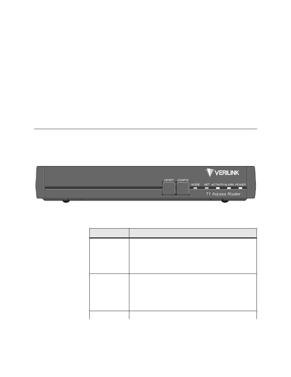
Front Panel
The front panel of the T1 Access Router (Figure 1.1) provides two
user-activated input control buttons and five LED status indicators that
provide access to unit configuration, diagnostics, and utilities.
Figure 1.1
Front Panel of T1 Access Router
The T1 Access Router’s front panel LED status indicators are defined in the
table below:
Indicator
Description
MODE
Normally, the
MODE
indicator lights green.
This indicator lights amber while configuration is being set by
the front panel buttons or when the configuration is changed by
SNMP or through the Web server interface. The indicator will
remain amber until the changed configuration is saved; it will
revert to green when the new configuration has been saved.
NET
The
NET
indicator is off (not illuminated) when the port has not
been configured.
The indicator lights red if the T1 link is down.and all configured
protocols on the link are established.
The indicator lights amber if the DDS link is operational but at
least one configured protocol on the link is down.
ACTIVITY