Virtual link table screen, Virtual link table screen -59 – Verilink T1 Access Router (34-00327) Product Manual User Manual
Page 87
W e b S e r v e r I n t e r f a c e
3-59
Values: Yes, No
Default: No
The Area Details screen provides the following user-activated buttons:
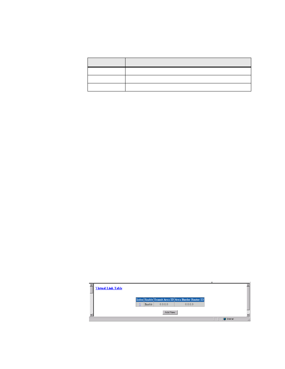
Virtual Link Table Screen
To permit maximum flexibility, OSPF allows the configuration of virtual links
to enable the backbone area to appear contiguous despite the physical reality.
In OSPF, the backbone is defined as an Area ID of 0.0.0.0. This backbone
cannot be disconnected in any way or some areas of the Autonomous System
become unreachable. This is because all inter-area traffic must go through the
backbone. In fact, the backbone is responsible for all inter-area routing
information distribution.
It is possible that an area cannot be connected directly to the backbone; in this
case a virtual link is used (Figure 3.50). To establish or maintain the
connectivity of the backbone, virtual links can be configured through non-
backbone areas. Basically, virtual links are used to connect components that
are otherwise not connected to the backbone.
A virtual link is treated by OSPF as a point-to-point unnumbered network
joining two area border routers. The virtual link must be configured in both of
the area border routers.
A virtual link is defined by the following two parameters:
•
The Router ID of the virtual link’s other endpoint.
•
The non-backbone that the virtual link crosses through.
Access this screen by selecting the Virtual Link Table from the OSPF
Parameters table on the IP Gateway screen.
Figure 3.50
Virtual Link Table Screen
Button
Function
Submit
Sets any values that have been changed.
Area Table
Returns you to the previous screen.
Delete Area
Deletes the currently defined Area.