Wavetronix SmartSensor 105 (SS-105) - User Guide User Manual
Page 20
CHAPTER 2 • CONNECTING POWER AND SURGE PROTECTION
19
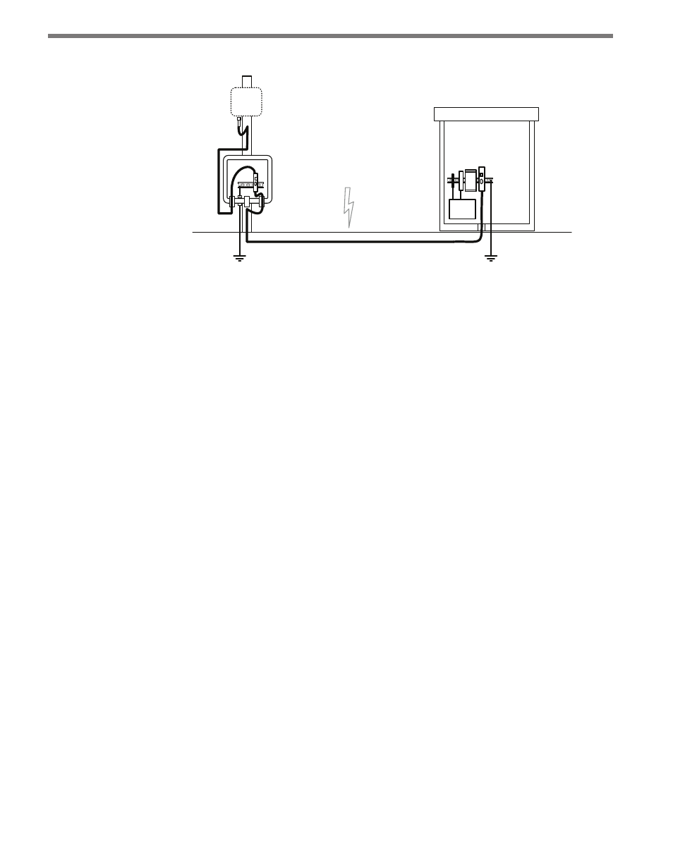
Sensor
Pole
Mount
Traffic
Cabinet
Main Traffic Cabinet
Both ends of the home-
run cable connect to the
UNPROTECTED side of the
surge modules
Figure 2.2 – Typical Cable Run
The Click 200 contains three terminal connectors on both the top and the bottom of the
module (see Figure 2.3). The terminal connectors are removable and are red-keyed, allow-
ing the connector to plug into only one specific jack. This both simplifies the wiring process
and reduces the possibility of wiring errors.
The back four terminals consist of one +DC power, -DC and two surge ground connec-
tions; the middle four terminals are for RS-485 communication and consist of a +485 con-
nection, a -485 connection, an RS-232 ground connection and a surge ground connection;
the front four terminals are for RS-232 communication and consist of TD, RD, CTS and
RTS.