Wavetronix SmartSensor 105 (SS-105) - User Guide User Manual
Page 26
CHAPTER 2 • CONNECTING POWER AND SURGE PROTECTION
25
2 Connect -DC (usually a black wire) to the GND screw terminal next to the +DC
terminal.
If the DC power comes from a Click 201/202 in the pole-mount cabinet that is surge pro-
tected using a Click 230, you can also connect power to the T-bus using a 5-position screw
terminal. To wire DC power directly into a 5-position screw terminal (see Figure 2.8):
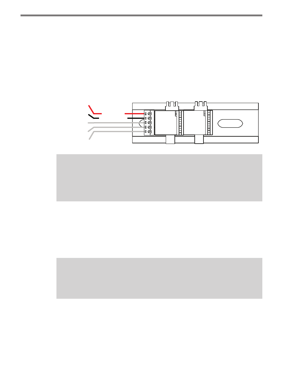
1 Connect +DC (24 VDC) to the top screw terminal.
2 Connect –DC to the second screw terminal.
3 Connecting Power Directly to the T-bus
+24 VDC
-DC
+485
-485
GND
(red wire)
(black wire)
(Green)
(Gray)
Note
Green T-bus connectors provide power and communication connectivity on the DIN
rail backplane; gray T-bus connectors only provide power connectivity and are used to
distribute power without connecting communication.
In the Main Traffic Cabinet
If DC voltage is sent across a homerun connection, AC power conversion is provided in the
main cabinet. In the main cabinet, the DC wires out of the Click 201/202 should be wired
to the PROTECTED side and the homerun cable should be connected to the UNPRO-
TECTED side of the Click 200.
Note
The purpose of the Click 200 in the main cabinet is not to protect the sensor, but the
electrical equipment inside of the main cabinet.
The last screw terminal block on the PROTECTED side of the Click 200 module contains
a +DC, -DC and two surge ground connections (see Figure 2.9).
1 Connect +DC (usually a red wire) to the +DC screw terminal.
2 Connect -DC (usually a black wire) to the GND screw terminal next to the +DC
terminal.