Wiring communication, Contact closure connections – Wavetronix SmartSensor 105 (SS-105) - User Guide User Manual
Page 27
26
CHAPTER 2 • CONNECTING POWER AND SURGE PROTECTION
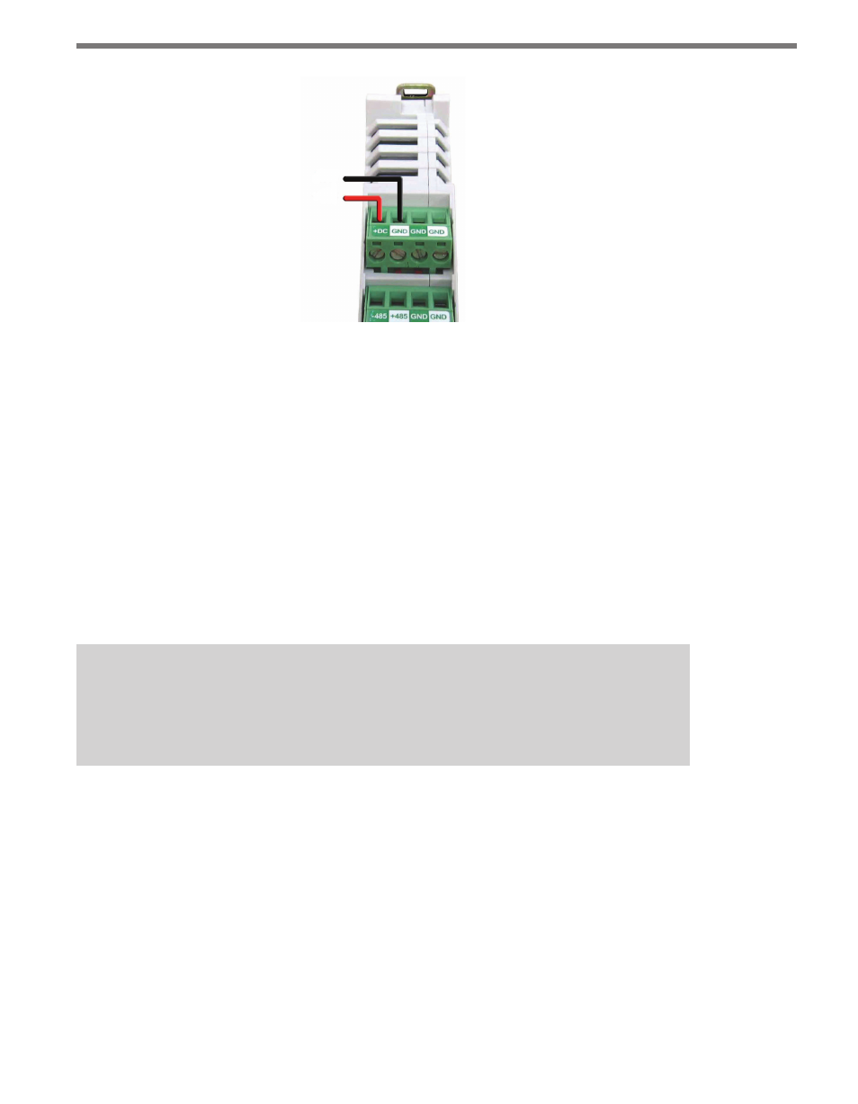
GND
+DC
Figure 2.8 – Wiring DC Power into the Click 200
Wiring Communication
After wiring the sensor cable into the PROTECTED side of the Click 200 in the pole
mount cabinet, two isolated serial connections are available. The sensor’s native RS-232
port is available via the DB-9 connector on the faceplate.
In addition, the sensor’s native RS-485 connection is available in the pole mount cabinet
via the following three ports on the Click 200:
˽
Screw terminals on the bottom
˽
RJ-11 connector on the faceplate
˽
T-bus backplane
Note
The Click 200 does not convert RS-232 communication to RS-485. It simply provides
surge protection for these two independent connections.
One common way to connect communications back to a main cabinet is to use a Smart-
Sensor cable as your homerun cable. See Appendix C for information about maximum
cable lengths for wired communication. Wavetronix Click products facilitate a wide variety
of additional wired and wireless communication options. Contact a Wavetronix-authorized
technical representative to find out which options are best suited for your application.
Contact Closure Connections
While any of the RS-485 ports on the Click 200 can be connected to contact closure mod-
ules, it is often easiest to connect from the RJ-11 port. In some cases, several contact closure
cards can be daisy-chained together. However, the chain should not be connected until each