Wavetronix SmartSensor 105 (SS-105) - User Guide User Manual
Page 93
Advertising
92
APPENDIX • SMARTSENSOR 105 USER GUIDE
Brown
CTS
Gray
232 GND
Table A.1 – 9-conductor Cable and Cabinet Connection
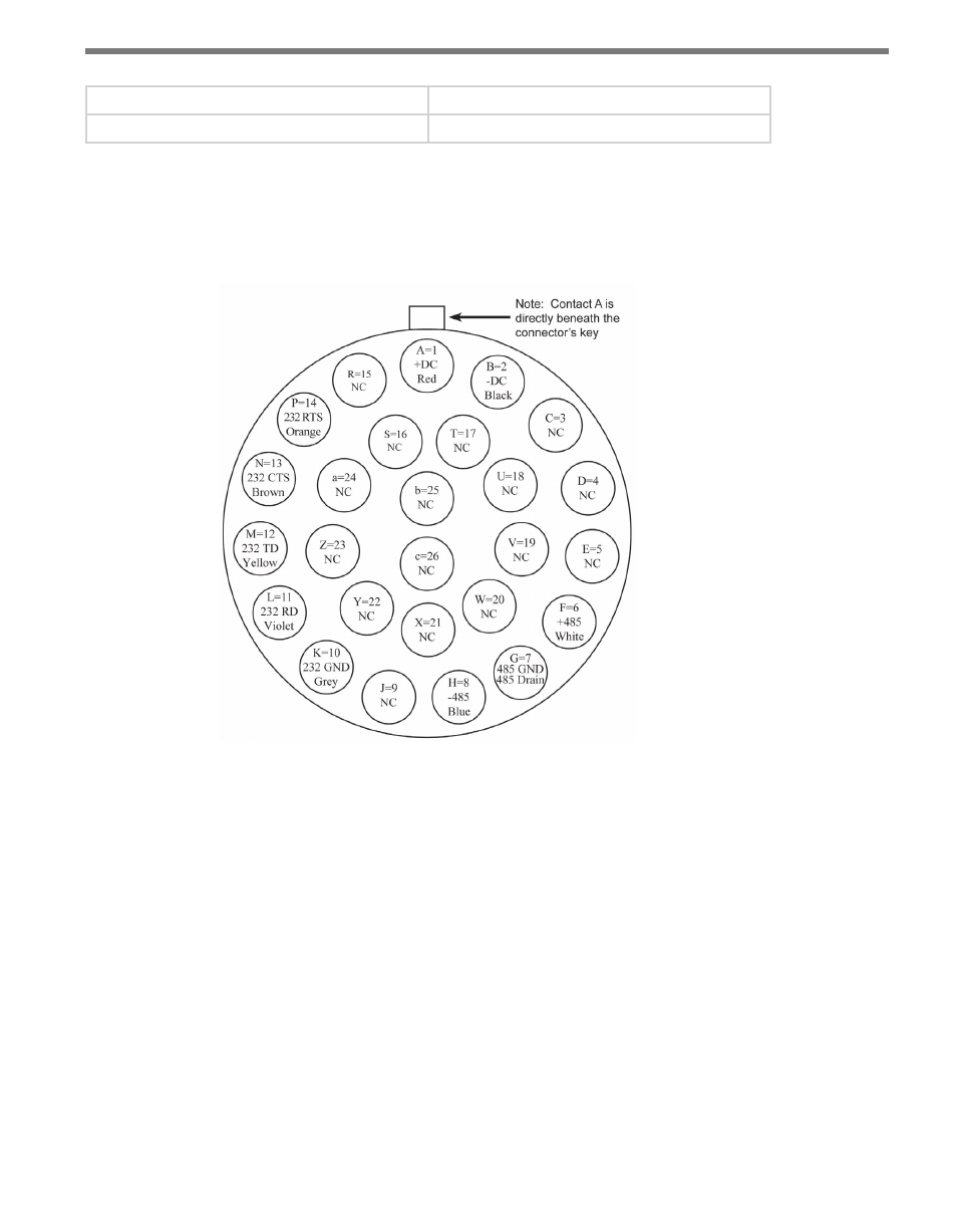
Figure A.1 shows a diagram of the 9-conductor cable’s 26-pin socket assignment. The
codes listed in the diagram are to be used to solder wires into the back of the plug where
the letters represent the individual solder cups.
Figure A.1 – SmartSensor 105 Plug Connector Socket Assignment
Figure A.2 shows the 9-conductor cable wire connections into a Click 200 surge protector.
Advertising