Wiring to earth ground – Wavetronix SmartSensor 105 (SS-105) - User Guide User Manual
Page 21
20
CHAPTER 2 • CONNECTING POWER AND SURGE PROTECTION
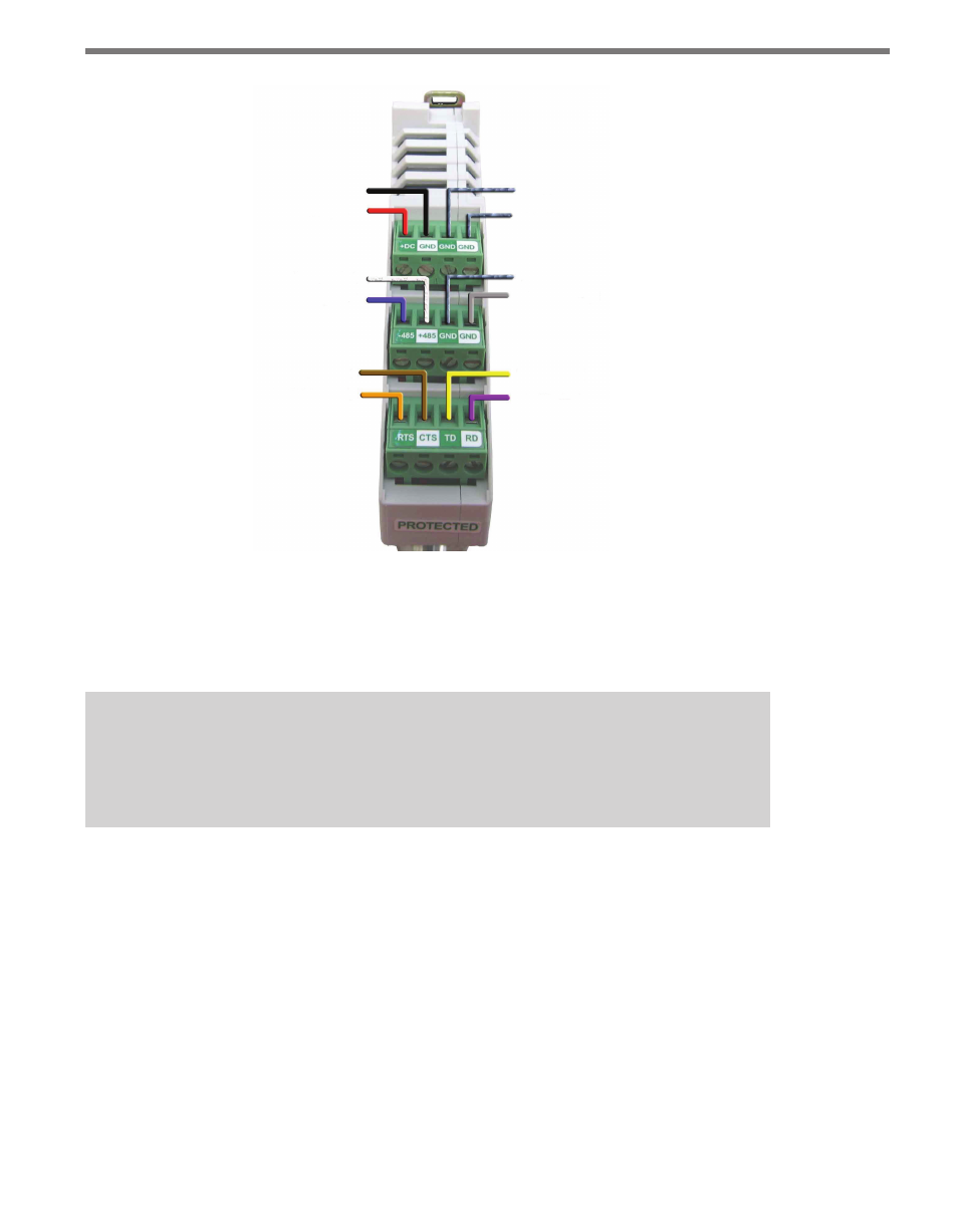
GND/-DC (Black)
+DC (Red)
+485 (White)
-485 (Blue)
CTS (Brown)
RTS (Orange)
Power Drain
232 Drain
485 Drain
Ground (Gray)
TD (Yellow)
RD (Purple)
Figure 2.3 – Surge Protected Terminal Connections (Top)
Figure 2.3 above shows the PROTECTED side of the Click 200. The UNPROTECTED
side of the Click 200 contains the same screw terminal connections, but are reversed from
left to right.
Note
See Appendix B for a description of how to wire the Click 200 using the old SmartSen-
sor cable as well as for a cable connector pin out diagram.
Wiring to Earth Ground
ALL Click 200 devices should be mounted on a DIN rail that is connected to earth ground
either through an earth-grounded chassis or a 16 AWG or larger grounding wire attached
to a 7-ft. (2.1-m) grounding rod. Follow the steps below to correctly wire to earth ground:
1 Connect the grounding wire from either the DIN rail or a GND screw terminal on
the UNPROTECTED side of the Click 200 to the lug bolt on the inside of the pole-
mount box.
2 Connect another grounding wire from the exterior lug bolt to earth ground (see Figure
2.4).