Wavetronix SmartSensor 105 (SS-105) - User Guide User Manual
Page 95
94
APPENDIX • SMARTSENSOR 105 USER GUIDE
Drain of Pair 4
232 GND
Pair 5
Reserved for future use
Red 6
CTS flow for 232
Black 6
RTS flow for 232
Table B.1 – Old Cable Description
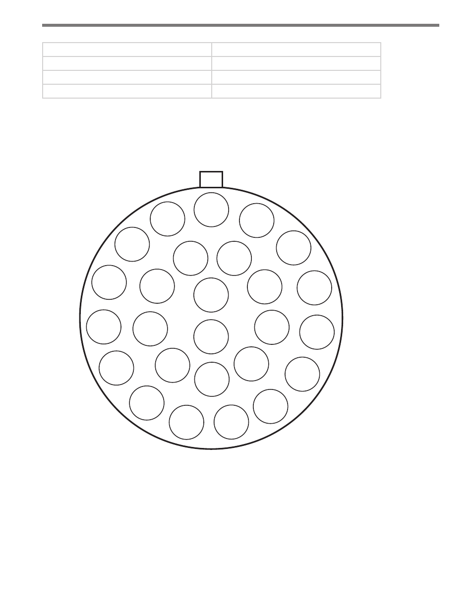
Figure B.1 shows a diagram of the old SmartSensor cable’s 26-pin socket assignment. The
codes listed in the diagram are to be used to solder wires into the back of the plug where
the letters represent the individual solder cups.
R=15
RS_DFM2
(R5)
P=14
232 RTS
(B6)
N=13
232 CTS
(R6)
M=12
232 TD
(R4)
a=24
RSVD
S=16
RS_DTM2
A=1
+DC
(R1)
B=2
-DC
(B1)
T=17
GND
(Drain 1)
C=3
+DC
(R2)
U=18
RSVD
b=25
NC
Z=23
RSVD
c=26
NC
V=19
RSVD
E=5
GND
(Drain 2)
L=11
232 RD
(B4)
Y=22
RSVD
X=21
GND
(Drain 5)
W=20
RSVD
F=6
+485
(R3)
K=10
232 GND
(Drain 4)
J=9
RSVD
H=8
-485
(B3)
G=7
485 GND
(Drain 3)
D=4
-DC
(B2)
Figure B.1 – Old SmartSensor Plug Connector Socket Assignment
Figure B.2 shows the old SmartSensor cable wire connections into a Click 200 surge pro-
tector.