Wavetronix SmartSensor 105 (SS-105) - User Guide User Manual
Page 24
CHAPTER 2 • CONNECTING POWER AND SURGE PROTECTION
23
3 Connect the neutral wire from the AC terminal block or cord to the terminal marked
1 on the Click 230.
4 Connect the ground wire from the AC terminal block or cord to the terminal marked
3 on the Click 230.
5 Connect the outgoing and protected line wire to the terminal marked 2 on the Click
230.
6 Connect the outgoing and protected neutral wire to the terminal marked 6 on the
Click 230.
The terminal blocks 3 and 4 are directly bonded via the metal mounting foot of the base
element to the DIN rail. There is no need for any additional grounding between terminals
3 and 4 and the DIN rail.
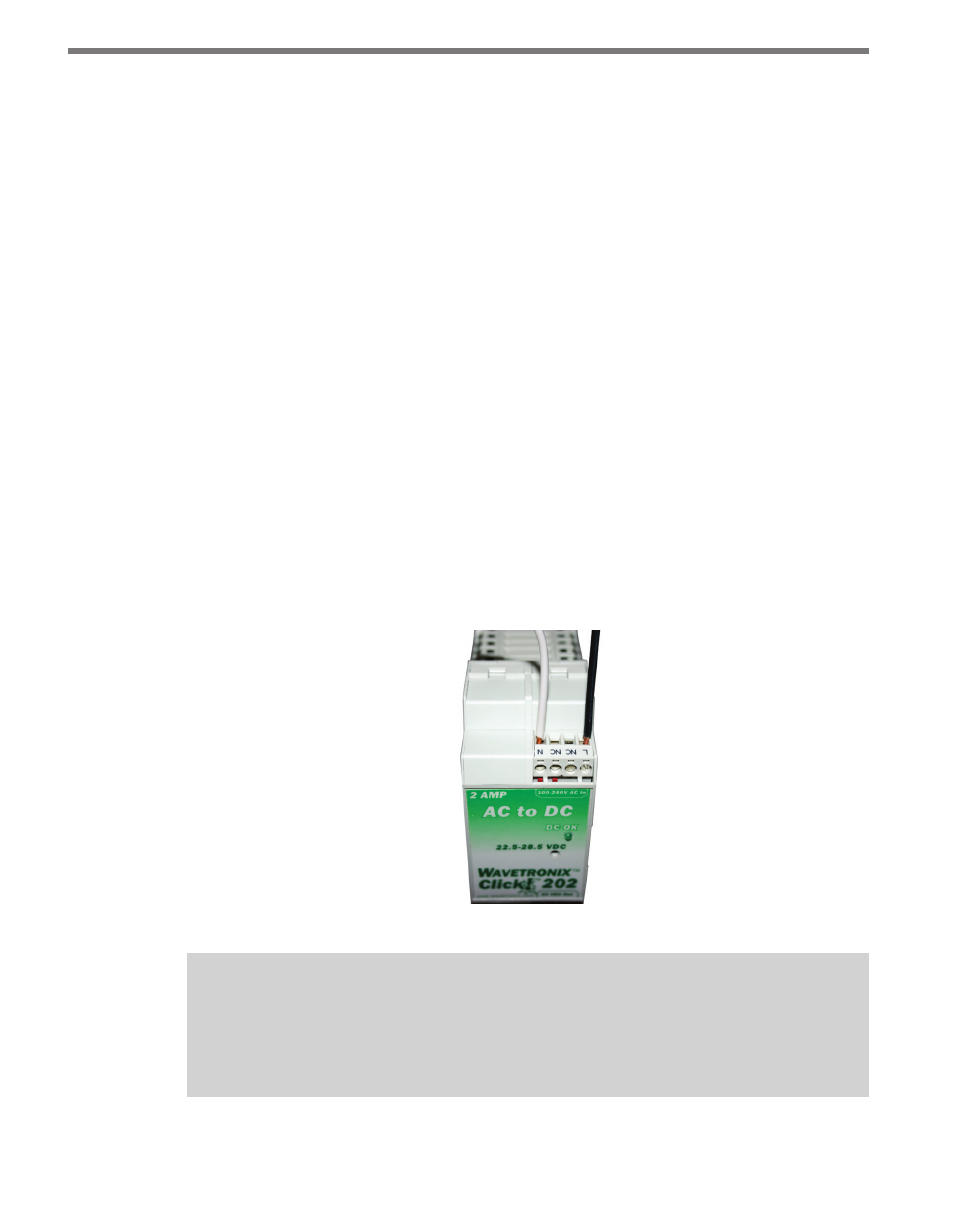
Wiring AC Power Into the Click 201/202
Follow the steps below to properly wire an AC to DC power conversion module (see Figure
2.6):
1 Mount the Click 201/202 onto the DIN rail.
2 Connect the line (hot) wire from the Click 230 into the L screw terminal on the top
of the Click 201/202. The line wire is usually black.
3 Connect the neutral wire from the Click 230 to the N screw terminal to the top of the
Click 201/202. The neutral wire is usually white.
Figure 2.6 – Wiring AC Power into the Click 201/202
Note
The NC screw terminal is not connected internally. Connecting a wire to a no connect
(NC) terminal simply gives it a convenient termination point.